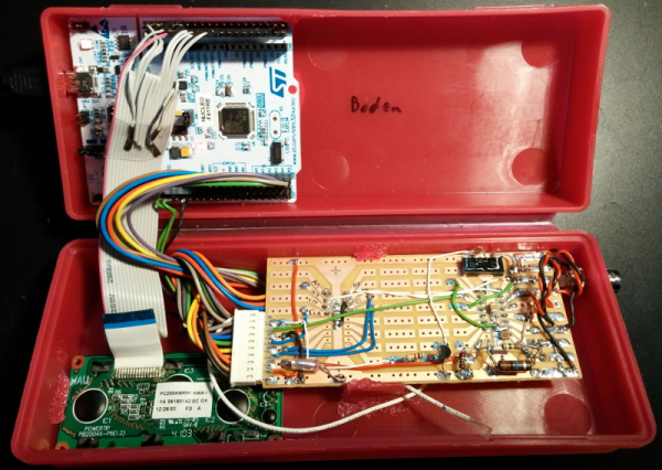

Like most hackers, I’ve run into a part that looks like it might do what I want, but the only documentation came from a company so thoroughly defunct their corporate office is now a nail salon and a Subway.
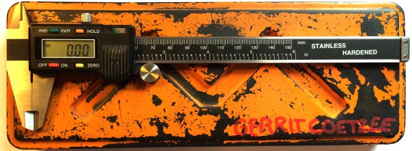
So, as any hacker who’s wandered through a discount store with a spare twenty, at one point I bought a Chinese caliper. Sure it measures wrong when the battery is low, the temperature has changed, if I’ve held it in my hand too long, the moon is out, etc. but it was only twenty dollars. Either way, how do I get accurate measurements out of it? Well, half-wizardry and telling yourself educated lies.
There are two golden rules to getting accurate measurements by telling lies. It may be obvious to some, but it took me quite a bit of suffering to arrive at them.
- Engineers are lazy. So lazy. Most things are going to be even numbers, common fractions, and if possible standard sizes. If sheets and screws come in 2 and 3mm then you bet you’re going to see a lot of 2mm and 3mm features. Also, even though the metric world is supposedly pure, you’re still going to see more 0.25 (1/4) mm measurements than you are .333333 (1/3) mm measurements. Because some small fractions are easier to think about than decimals.
- Your eyes lie. If it matters, measure it to be sure.
Continue reading “Measuring Parts Badly For Accurate Reverse Engineering”