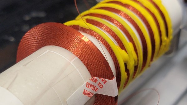
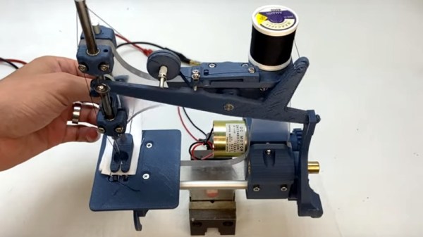
As ferrite technology has progressed into a mastery of magnetic permeability, the size of inductors has gone down to the point at which they are now fairly nondescript components. There was a time though when inductors could be beautiful creations of interleaving layers of copper wire in large air-cored inductors, achieved through clever winding techniques. It’s something that’s attracted the attention of [Brett], who’s produced a machine capable of producing something close to the originals.
Part of the write-up is an investigation of the history, these coils were once present even at the consumer level but are now the preserve of only a few highly secretive companies. They are still worth pursuing though because they can deliver the high “Q” factor that is demanded in a high quality tuned circuit. The rest of the write-up dives in detail into the design of the wire feeder, and the Arduino motor control of the project. There should be enough there for any other experimenters to try their hands at layered inductors, so perhaps we’ll see this lost art make a comeback.
Custom coils are a regular requirement for anything from radios, to musical instruments, to switching power supplies, so it’s not surprising that quite a few projects featuring them have made it here. One of the more unusual of late has been one that winds toroids.
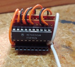 They reverse-engineered the motor driver connections – those go through a 74HC245 buffer between the original CPU and the drivers. Initially, they put an Arduino inside the control box of the CNC and it fit nicely, but it turned out the Arduino’s CPU would restart every time the spindle spun up – apparently, EMC would rear its head. So, they placed the Arduino out of the box, and used two CAT7 cables to wire up the motor and endstop signals to it.