[Stephen] has just shared with us the current progress of his night vision vehicle system, and it’s looking quite promising!
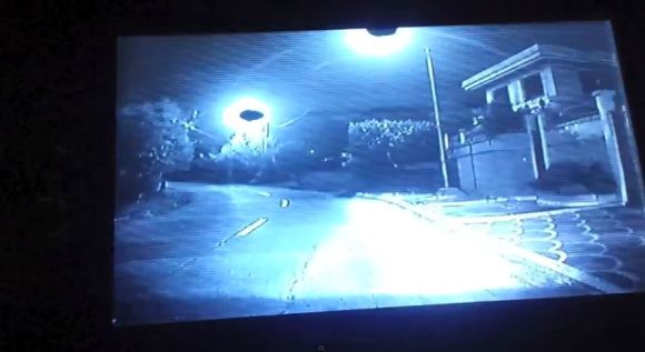
The idea of the project is to provide the driver with a high contrast image of the road, pedestrians and any other obstacles that may not be immediately visible with headlights. It’s actually becoming a feature on many luxury cars including BMW, Audi, GM and Honda. This is what inspired [Stephen] to try making his own.
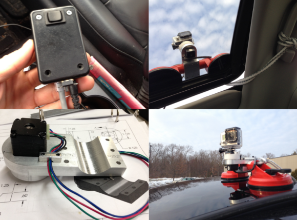
The current system consists of an infrared camera, two powerful IR light spot lights, and a dashboard LCD screen to view it. It may be considered “not a hack” by some of our more exuberant readers, but [Stephen] does such a great job explaining his future plans for it, which include object recognition using OpenCV, so we felt it was more than worth a share, even at this point.
You see, the idea of vehicle night vision is not to constantly watch a little screen instead of the road — it’s designed to be there when you need it — and to let you know when you need it, [Stephen’s] planning on adding a Raspberry Pi to the mix running OpenCV to detect any anomalies on the road that could be of concern. We shudder at the amount of training a system like that might need — well, depending on the complexity of this image recognition.
Anyway, stick around after the break to hear [Stephen] explain it himself — it is a long video, but if you want to skip to the action there are clips of it on the road at 1:53 and 26:52.
Continue reading “The Beginning Of A DIY Vehicle Night Vision System” →