A Masochistic Video Card

Have a penchant for pain? Why not destroy your fingertips with a wire-wrap tool building a video card made entirely out of discrete components.

When [Chris] decided to build an entry for the Dangerous Prototypes 7400 logic competition he already had his hands full. The 74xx chips he had on hand had a maximum clock frequency of 25MHz, but the VGA pixel clock runs at 40MHz. dividing the H sync timing by 4 means the maximum speed required of the video card is only 10MHz, albeit with a reduced resolution.

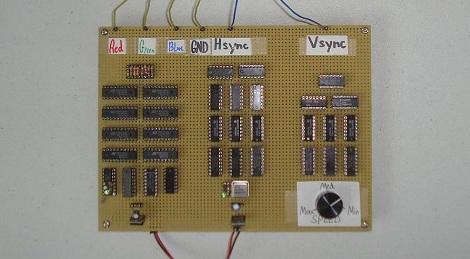
The video card was constructed on perfboard with wirewrap sockets. An 8-bit DAC was included, allowing the card to display 256 separate colors but only the three primary lines were wired up to the VGA cable. As is, the card cycles through 8 different colors in a constant loop, not bad for a pile of chips.

VGA out has been done on everything from an ARM to an ATtiny, but rarely, if ever, has VGA been done with discrete components. While this video card may not be our first choice for bitcoin mining, it’s still a very impressive build. Check out the walk through video after the break.

Continue reading “A Masochistic Video Card”

Hack A Watchman

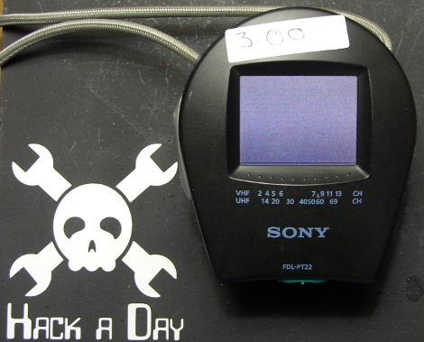
I have been on the hunt in our local thrift and random junk stores lately for a small TV to hopefully modify into a decent enough computer monitor for my Apple //C and Trash80. While there are TONS of TV’s out there, none were really striking me in tube size or picture quality. Roaming around the last resource I happened to find this tiny Sony Watchman Color LCD TV.

Of course this thing is way too tiny for a computer monitor. I thought it would be a great thing to have around the bench for when I am repairing a video game system, or messing about with the TV out Arduino library (the 3 buck price tag on half off day didn’t help either). Directly out of the store this thing is totally useless as there are no inputs and its tuner is for analog “over the air” stations which no longer exist.

Join me after the break to see how I turned this buck fifty paperweight into a functional bench tool!

Continue reading “Hack A Watchman”

Get Digital Plastic Surgery Thanks To OpenFrameworks And Some Addons

[Kyle McDonald] is trying out a new look, at least in the digital world, with the help of some openFrameworks video plugins. He’s working with [Arturo Castro] to make real-time facial substitution as realistic as possible. You can see that [Arturo’s] own video has a different take on shading and color of the facial alterations that makes them a bit less realistic than what [Kyle] was able to accomplish (see that clip after the break).

The setup depends on some facial tracking software developed by [Jason Saragih]. That package is wrapped in ofxFaceTracker (already linked at the top of this article) which makes it play nicely with openFrameworks. From there, it’s just a matter of image processing. If you think you’re up to the challenge, grab your own copies of the source code and get to work. We’re shocked by how real this looks, even when [Kyle] grabs his cheeks and stretches them out. If someone can fix some of the artifacts around the edges of the sampled faces this would be ready to use when video-conferencing.

It kind of makes us think of technology seen in The Running Man.

Continue reading “Get Digital Plastic Surgery Thanks To OpenFrameworks And Some Addons”

Video: Soldering Our PIC Development Board

For those of you who followed along with our Eagle CAD series, here is the final payoff where we assemble the circuit board that was designed. In this video, [Jack] explains where things will go on the board and then shows you how to solder the parts. For the advanced folks out there who haven’t moved to solely surface mount parts when you can get away with it, he shows an easy way to solder the processor, which is a TQFP-44 part. This can seem like a daunting task but it really isn’t.

If you would like to make your own board like this, you can find the files here. Please note that although this board shouldn’t have any issues, we haven’t tested it ourselves yet. [Jack] is going to do some videos about a different topic for a few weeks but will pick back up with this board again when they are done.

Video is after the break. Continue reading “Video: Soldering Our PIC Development Board”

Video: Eagle CAD Layout

This week’s video is the last in a series of videos where we show how to use Eagle CAD. Today we will look a the Layout portion of the program and will create a circuit board from the schematic that we created previously. We start by creating a layout file and then moving all of the parts to appropriate places on the circuit board. After that, [Jack] shows how to route the traces. Along the way, he talks about the tools that he is using and various ways to use them. The end result is a prototyping board for the PIC18F44J11.

Like the others, this video is fairly long at 29 minutes, so make sure to have some time dedicated towards watching it if you do.

In next week’s video, we will be showing this board as it arrived to us from a manufacturer and will do a tutorial on how to solder.

If you have missed our previous videos, you can find them here:

Schematic part I
Schematic and Custom part creation
CAM Processor

We have also created many supplemental videos explaining how to use many of the tools in the tool palettes. You can find them on our Youtube channel:

Check out the video after the break!
Continue reading “Video: Eagle CAD Layout”

Video – Eagle CAD’s CAM Processor

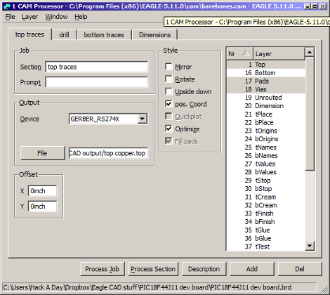
Here is the next installment in our series of Eagle CAD videos. In this video we skip ahead a bit and show off the CAM processor that you use to create the files necessary to have your circuit boards be manufactured. After watching this video, you will know how create a new CAM program, load a circuit board into the CAM processor, tell it where to save your files, and actually use it to create the files.

We’re skipping ahead today because of a screw up on our part. We meant to show the layout portion of the program today but edited the wrong video… We’ll show layout next week. After that, we will show the completed circuit board and solder the parts onto it.

If you are itching for some Eagle CAD layout info, you may be interested in some supplementary videos that we have uploaded to our Youtube channel. In those videos, we show how to use the most important features in the layout portion of the Eagle CAD.

Have you missed the previous videos? Here are some links to them:

Schematic and the beginning of a custom part: [click here]
More custom part stuff: [click here]

Video is after the break:
Continue reading “Video – Eagle CAD’s CAM Processor”

Putting Laptop LCDs To Use With An FPGA

We’re always impressed with the number of laptop displays we’re able to pick out of the trash. Most of the time the computer is borked beyond repair so we end up with a lot of functional but unusable LCD panels. As a service to us all, [EiNSTeiN_] figured out how to control an LCD panel using a cheap homebrew FPGA board.

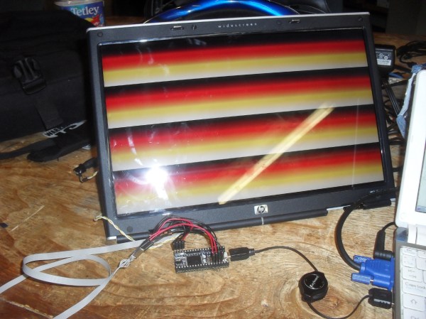
LCD panels don’t use a simple protocol like VGA for turning pixels on and off. Instead, the very high-speed LVDS is used. LVDS is beyond the capabilities of simple microprocessors, so [EiNSTeiN_] built himself a clone of an XuLA FPGA prototyping board and set to work. After figuring out the signal lines to the panel, [EiNSTeiN_] pored over the timing diagrams for the LVDS controller and the LCD panel. From the data sheets, he figured out data is usually sent to the panel at about 500 MHz. The homebrew FPGA board couldn’t manage that speed so [EiNSTeiN_] cut the FPGA clock in half.

While LCD’s 60 fps refresh rate was reduced to 30 fps, [EiNSTeiN_] says there’s only a little flicker. Not bad for something that could have easily been trashed.