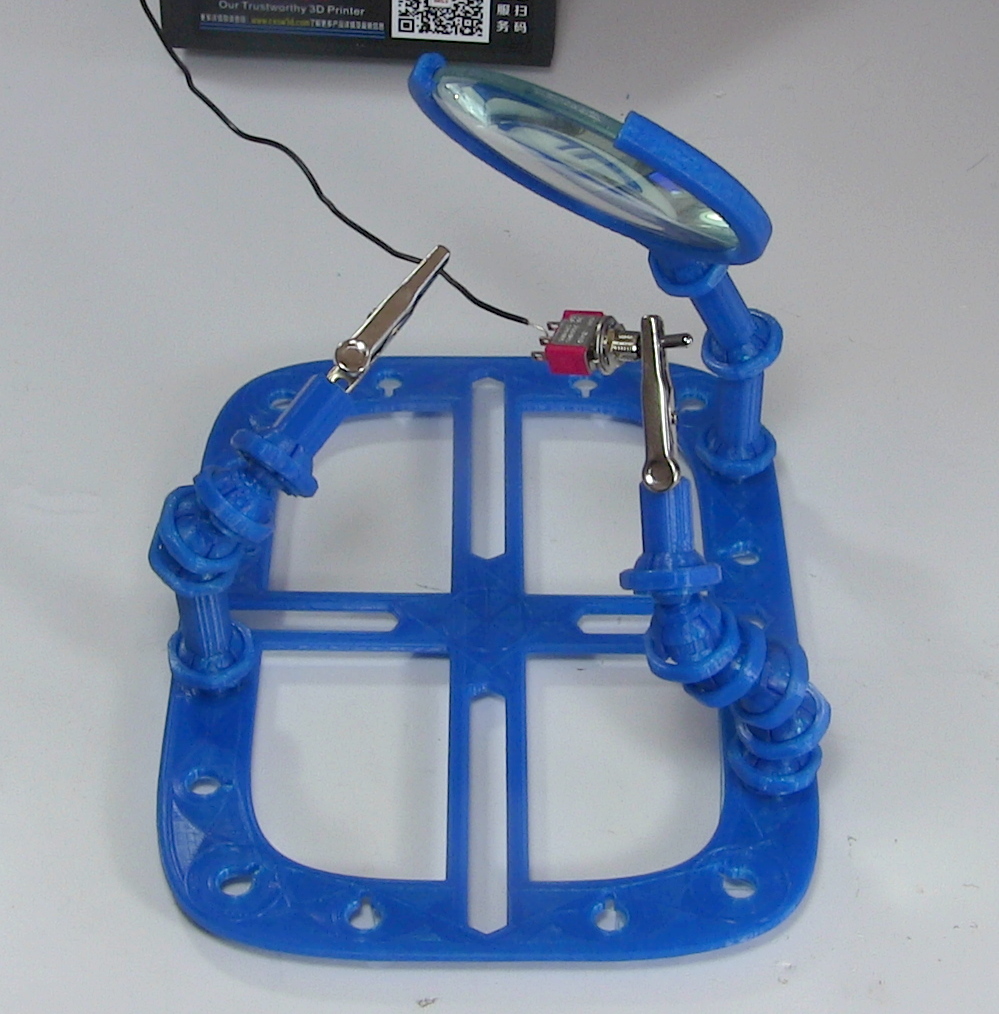
In one hand you hold the soldering iron, in the other the solder, and in two more hands the parts you’re trying to solder together. Clearly this is a case where helping hands could be useful.
One reason is to take advantage of standardized, open source creativity. Anyone can share a model of their design for all to use as is, or to modify for their needs. A case in point is the ball and socket model which I downloaded for a helping hand. I then drew up and printed a magnifying glass holder with a matching socket, made a variation of the ball and socket joint, and came up with a magnetic holder with matching ball. Let’s takea look at what worked well and what didn’t.
Of all the parts on your average desktop 3D printer, the nozzle itself is arguably where the real magic happens. Above the nozzle, plastic is being heated to the precise temperature required to get it flowing smoothly. Immediately below the nozzle there’s a fan blowing to get the plastic cooled back down again. This carefully balanced arrangement of heating and cooling is the secret that makes high quality fused deposition modeling (FDM) printing possible.
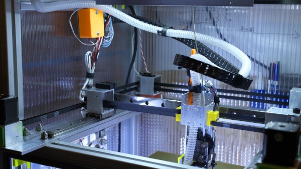
But as it turns out, getting the plastic hot ends up being easier than cooling it back down again. The harsh reality is that most of the fans small enough to hang on the side of a 3D printer nozzle are pretty weak. They lack the power to push the volume of air necessary to get the plastic cooled down fast enough. But with his latest project, [Mark Rehorst] hopes to change that. Rather than using some anemic little fan that would be better suited blowing on the heatsink of a Raspberry Pi, he’s using a hacked CPAP machine to deliver some serious airflow.
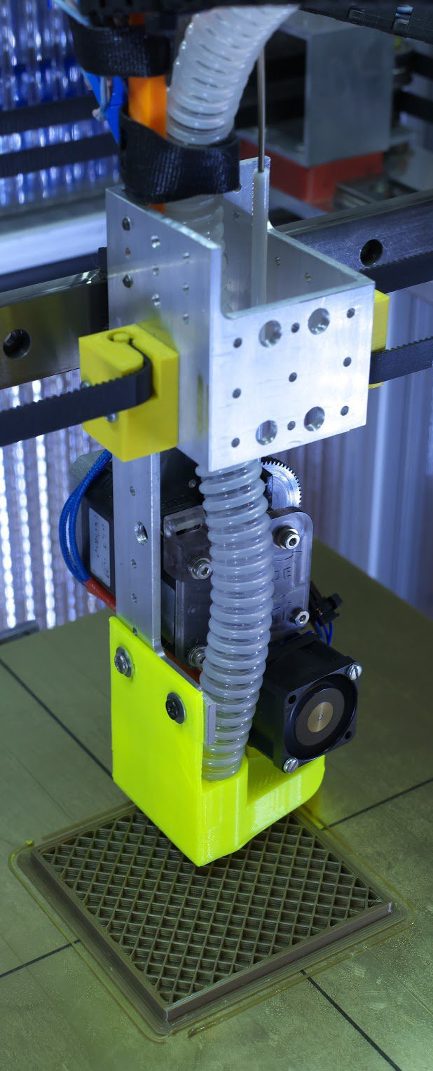
The brilliance of using a CPAP machine for this hack is two-fold. For one, the machine uses a powerful centrifugal fan rather than the wimpy axial “muffin” fans we usually see on 3D printers. Second, the CPAP pushes air down a lightweight and flexible hose, which means the device itself doesn’t have to be physically mounted to the printer head. All you need is manifold around the printer’s nozzle that connects up to the CPAP hose. This “remote” fan setup means the print head is lighter, which translates (potentially) into higher speed and acceleration.
[Mark] was able to connect the fan MOSFET on his printer’s SmoothieBoard controller up to the brushless motor driver from the CPAP motor, which lets the printer control this monster new fan. As far as the software is concerned, nothing has changed.
He hasn’t come up with a manifold design that’s really optimized yet, but initial tests look promising. But even without a highly optimized outlet for the air, this setup is already superior to the traditional part cooler designs since it’s got more power and gets the fan motor off of the print head.
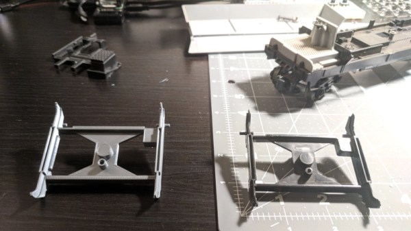
Model railways are a deep and rewarding hobby, and the mechanisms involved can be both surprisingly intricate and delightful. A great example that may surprise the unfamiliar is that of model train carriages, such as coal cars, that are capable of both receiving and dumping a load at various points on a model layout. This adds realism and, if we’re honest, just plain old fun.
This is the perfect example of a tidy repair executed through 3D printing. The broken part was extremely detailed and would be difficult and expensive to repair or fabricate through other measures. However, through the power of 3D printing, all that’s required is a 3D modelling job and a few hours to print it.
It’s a great entry into our Repairs You Can Print challenge, and covers the fundamentals of modelling and iterative design well. Got a neat repair you’ve done yourself? Document it on Hackaday.io and enter yourself!
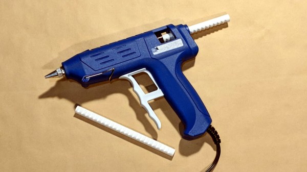
When is a hot glue stick not a hot glue stick? When it’s PLA, of course! A glue gun that dispenses molten PLA instead of hot glue turned out to be a handy tool for joining 3D-printed objects together, once I had figured out how to print my own “glue” sticks out of PLA. The result is a bit like a plus-sized 3D-printing pen, but much simpler and capable of much heavier extrusion. But it wasn’t quite as simple as shoving scrap PLA into a hot glue gun and mashing the trigger; a few glitches needed to be ironed out.
Why Use a Glue Gun for PLA?
Some solutions come from no more than looking at two dissimilar things while in the right mindset, and realizing they can be mashed together. In this case I had recently segmented a large, hollow, 3D model into smaller 3D-printer-sized pieces and printed them all out, but found myself with a problem. I now had a large number of curved, thin-walled pieces that needed to be connected flush with one another. These were essentially butt joints on all sides — the weakest kind of joint — offering very little surface for gluing. On top of it all, the curved surfaces meant clamping was impractical, and any movement of the pieces while gluing would result in other pieces not lining up.
An advantage was that only the outside of my hollow model was a presentation surface; the inside could be ugly. A hot glue gun is worth considering for a job like this. The idea would be to hold two pieces with the presentation sides lined up properly with each other, then anchor the seams together by applying melted glue on the inside (non-presentation) side of the joint. Let the hot glue cool and harden, and repeat. It’s a workable process, but I felt that hot glue just wasn’t the right thing to use in this case. Hot glue can be slow to cool completely, and will always have a bit of flexibility to it. I wanted to work fast, and I wanted the joints to be hard and stiff. What I really wanted was melted PLA instead of glue, but I had no way to do it. Friction welding the 3D-printed pieces was a possibility but I doubted how maneuverable my rotary tool would be in awkward orientations. I was considering ordering a 3D-printing pen to use as a small PLA spot welder when I laid eyes on my cheap desktop glue gun.
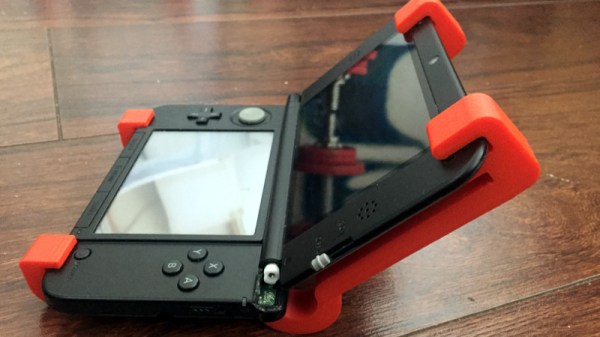
Handheld game consoles have a hard life, and even the most well-built models can sometimes fail. The Nintendo 3DS XL, for example, can fail at its hinge, which is what happened to the one owned by [Mark]. Would he fix the hinge? No, he had a far simpler if a little less flexible solution, a 3D-printed bracket that clips over the whole device.
Sometimes the best pieces of work are also the simplest ones, and this one certainly fits that bill on both counts. When your console dies, you want it fixed, and though this doesn’t extend as far as providing a working hinge action it should allow you to play without further damaging anything. It’s not impossible to imagine that it could be made to incorporate a flexible zig-zag section to produce a closeable hinge, but if your Nintendo is broken you’ll care little for such niceties. The project can be downloaded from its Thingiverse page.
A common failure that we’d expect to accompany a broken hinge would be a faulty flexible ribbon cable. Fortunately, those are fixable on the 3DS, too.
Filament-based 3D printers are remarkably wasteful. If you buy a kilogram of filament from your favorite supplier, the odds are that it will come wrapped around a plastic spool weighing about 250 grams. Use the filament, and that spool will be thrown in the trash. Very, very few products have such wasteful packaging as 3D printer filament, with the possible exception of inkjet cartridges or getting a receipt with your purchase at CVS.
For the last few years, [Richard Horne], better known as RichRap, has been working towards a solution to the problem of the wasteful spools for 3D printer filament. Now, it looks like he has a solution with the MakerSpool. It’s the perfect solution for a 3D printing ecosystem that doesn’t waste 20% of the total plastic on packaging.
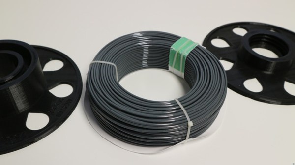
The design of the MakerSpool is fairly straightforward and also 3D printable. It’s a plastic filament spool, just a shade over 200mm in diameter, consisting of two halves that screw together. Add in some RepRap ‘teardrop’ logos, and you have a spool that should fit nearly any machine, and will accept any type of filament.
The trick with this system is, of course, getting the filament onto the spool in the first place. Obviously, filament manufacturers would have to ship unspooled filament that’s somehow constrained and hopefully vacuum packed. Das Filament, a filament manufacturer out of Germany, has already tested this and it looks like they have their process down. It is possible to ship a kilogram of 1.75 filament without a spool, and held together with zip ties. Other filament manufacturers also have packaging processes that are amenable to this style of packaging.
Whether this sort of packing will catch on is anyone’s guess, but there are obvious advantages. There is less waste for the environmentalists in the crowd, but with that you also get reduced shipping costs. It’s a win-win for any filament manufacturer that could also result in reduced costs passed onto the consumer.
The Repairs You Can Print Contest on Hackaday.io is a challenge to show off the real reason you bought a 3D printer. We want to see replacement parts, improved functionality, or a tool or jig that made a tough repair a snap. Think of this as the opposite of printing low poly Pokemon or Fallout armor. This is a contest to demonstrate the most utilitarian uses of a 3D printer. Whether you fixed your refrigerator, luggage, jet engine, vacuum cleaner, bike headlight, or anything else, we want to see how you did it!
The top twenty projects in the Repairs You Can Print contest will be rewarded with $100 in Tindie credit. That’s a Benjamin to spend on parts, upgrades, and components to take your next project to the next level!
Students and Organizations Can Win Big
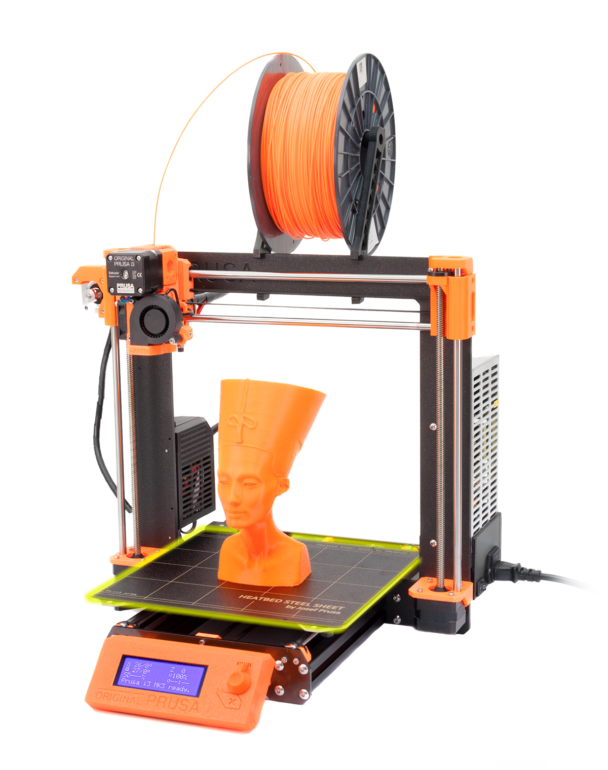
The Best Student and Best Organization will win a Prusa i3 MK3!
This contest is open to everyone, but we’re also looking for the best projects to come from students and hackerspaces. We’ll be giving away two amazing 3D printers to the best Student entry and best Organization entry. These two top projects will be awarded an Original Prusa i3 MK3 with the Quad Material upgrade kit. This is one of the finest 3D printers you can buy right now, and we’re giving these away to the best student, hackerspaces, robotics club, or tool lending library.
If you have a project in mind, head on over to Hackaday.io and create a project demonstrating your 3D printed repair!
What is This Contest All About?
This contest is all about Repairs You Can Print, but what does that actually mean? Instead of printing Pokemon or plastic baubles on your desktop CNC machine, we’re looking for replacement parts. We’re looking for commercial, off the shelf items that were broken, but repaired with the help of a 3D printer. Is your repair good enough to show off as part of the contest? Yes! That’s the point, we want to see the clever repair jobs that people often don’t spend much time talking about because they just work.
Need some examples? Sure thing.
The underside of a vacuum cleaner
A 3D printed wheel for a broken vacuum cleaner
A while back, [Elliot Williams], one of the fantastic Hackaday Editors, had a broken vacuum cleaner. The wheels were crap, but luckily they were designed as a single part that snaps into a swivel socket. Over six or so years, the original wheels in this vacuum gave out, but a replacement part was quickly printed and stuffed into the socket. The new wheels have been going strong for a year now. That’s an entire year of use for a vacuum for five cents worth of plastic and an hour’s worth of printing time.
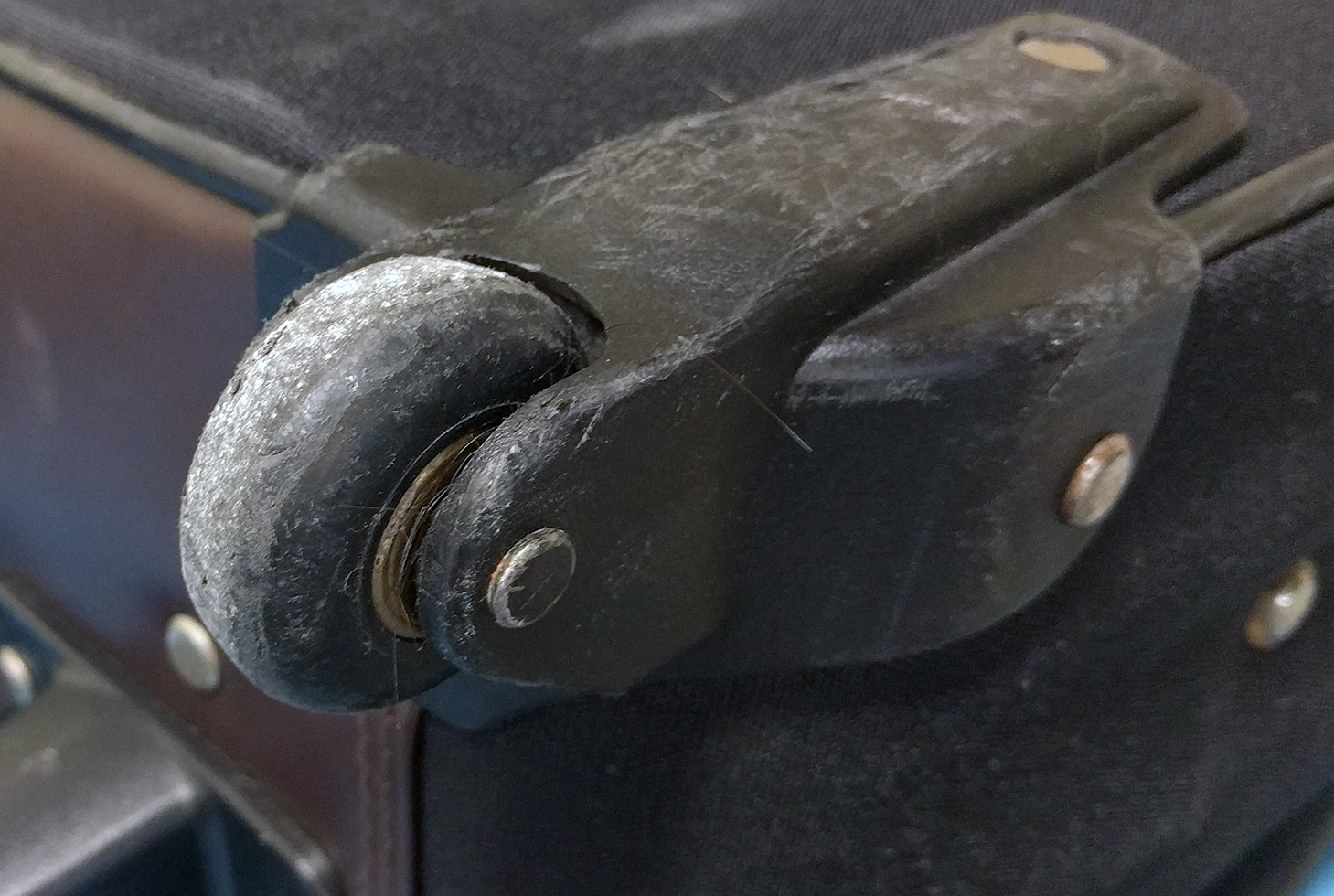
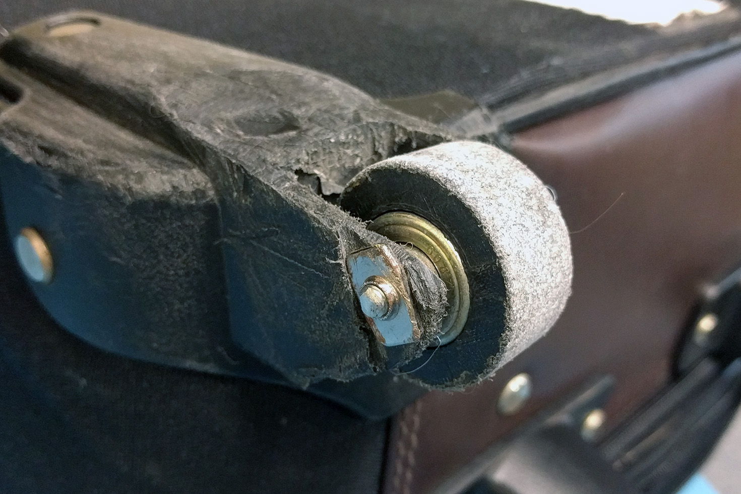
The stock wheel on my luggage
A 3D printed wheel on my luggage. The original was destroyed at either ORD or PHL.
Need another example? My suitcase was apparently dragged behind a luggage cart for miles at either ORD or PHL. When it arrived on the baggage carousel, one wheel was shredded, and the wheel mount was ground down to almost the axle. The rest of the bag was still good, and I just removed the old wheel, salvaged the bearings, and printed a new wheel out of PLA. This suitcase has now traveled 60,000 miles with a 3D printed wheel, and it’s only now looking worse for wear.
How To Get In On The Action
We’re looking for the best repairs, jigs, and tools you’ve ever printed. To get started, head on over to Hackaday.io, create a new project, and document your repair. The Repairs You Can Print contest will run from Tuesday, January 16th, 2018 through 12 PM PST Tuesday, February 20th, 2018. Here’s a handy count down timer for ‘ya.

 Some solutions come from no more than looking at two dissimilar things while in the right mindset, and realizing they can be mashed together. In this case I had recently segmented a large, hollow, 3D model into smaller 3D-printer-sized pieces and printed them all out, but found myself with a problem. I now had a large number of curved, thin-walled pieces that needed to be connected flush with one another. These were essentially butt joints on all sides — the weakest kind of joint — offering very little surface for gluing. On top of it all, the curved surfaces meant clamping was impractical, and any movement of the pieces while gluing would result in other pieces not lining up.