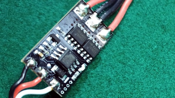
Reverse Engineering The Sound Blaster

The first sound card to output PCM audio — the kind you need for audio samples — wasn’t the Sound Blaster. The AdLib Music Synthesizer Card could output PCM audio over software. The AdLib card also cost $200 at the time of its release. This was too much for some, and in time the Creative Labs Sound Blaster was released for the rock-bottom price of $125. This was a more capable card, and in the years since prices on the used market have gone through the roof. In 1990, you could buy a Sound Blaster for a Benjamin and a half, in 2019, prices on eBay are reaching and exceeding $400.

With the prices of used cards so high, we start to get into the territory where it starts to make sense to reverse engineer and re-manufacture the entire card. This hasn’t been done before, but that’s no matter for [Eric Schlaepfer], or [@TubeTimeUS]; he’s done crazier projects before, and this one is no different.

In reverse-engineering the Sound Blaster, there are a few necessary components. The Sound Blaster had an OPL2 chip for sound synthesis, which you can get through various vendors. The trick, though, is the microcontroller. This is really just an 8051 with a custom mask ROM.

The goal of this project is actually just to dump the ROM on the Intel 8051-alike microcontroller. This is something that’s relatively commonly done in high-tech labs, and luckily the Bay Area has [John McMaster], the guy who will take you into his lab and strip a die from its epoxy. Looking at the chip under the microscope, it was discovered the mask ROM on this chip was an implant ROM, with the ones and zeros represented by invisible ions in the substrate itself. There was no hope of reverse-engineering this chip from a purely visual inspection, but there was a sense amplifier on one of the data lines. By probing this sense amplifier while running through the address space, [Eric] was able to dump all the bytes of the ROM one bit at a time.

However, and there’s always a however, there are clone Sound Blasters out there, usually from China, and you can dump these chips if you’re lucky enough to get your hands on one. [Eric] reached out to the community and found these clone microcontrollers didn’t have the code protect bit set; dumping these was easy. This ROM was compared to the work [Eric] did with the sense amplifier, and after figuring out the order of the bits, it was found the code matched. The code was successfully cloned, and now new Sound Blasters can be made. Don’t tell eBay that, because someone is trying to sell one of [Eric]’s clone cards for $180.

All the code, files, materials, and everything needed to clone a Sound Blaster can be found in [Eric]’s GitHub, although there are a few open questions as to what’s going on in the Sound Blaster’s microcontroller. There’s a ‘secret’ 512-byte ROM on the die, and no one outside of an Intel NDA knows what it does. This could be used for a manufacturing test, but who knows. Other than that, there are a few features in the code that weren’t used, like previously unknown DSP commands, an ADPCM lookup table, and a routine that plays from SRAM without using DMA. It’s a deep dive into the inner workings of the most popular sound card of all time, and it’s quite simply amazing.

Universal Chip Analyzer: Test Old CPUs In Seconds

Collecting old CPUs and firing them up again is all the rage these days, but how do you know if they will work? For many of these ICs, which ceased production decades ago, sorting the good stuff from the defective and counterfeit is a minefield.

Testing old chips is a challenge in itself. Even if you can find the right motherboard, the slim chances of escaping the effect of time on the components (in particular, capacitor and EEPROM degradation) make a reliable test setup hard to come by.

Enter [Samuel], and the Universal Chip Analyzer (UCA). Using an FPGA to emulate the motherboard, it means the experience of testing an IC takes just a matter of seconds. Why an FPGA? Microcontrollers are simply too slow to get a full speed interface to the CPU, even one from the ’80s.

So, how does it actually test? Synthesized inside the FPGA is everything the CPU needs from the motherboard to make it tick, including ROM, RAM, bus controllers, clock generation and interrupt handling. Many testing frequencies are supported (which is helpful for spotting fakes), and if connected to a computer via USB, the UCA can check power consumption, and even benchmark the chip. We can’t begin to detail the amount of thought that’s gone into the design here, from auto-detecting data bus width to the sheer amount of models supported, but you can read more technical details here.

The Mojo v3 FPGA development board was chosen as the heart of the project, featuring an ATmega32U4 and Xilinx Spartan 6 FPGA. The wily among you will have already spotted a problem – the voltage levels used by early CPUs vary greatly (as high as 15V for an Intel 4004). [Samuel]’s ingenious solution to keep the cost down is a shield for each IC family – each with its own voltage converter.

Continue reading “Universal Chip Analyzer: Test Old CPUs In Seconds”

The Most Flexible Synthesizer Is DIY, Raspberry Pi

[Ivan Franco] sent us this great synthesizer project that he’s working on. Or maybe it’s more like a synthesizer meta-project: a synthesizer construction set. You see, what Pryth has is a Raspberry Pi inside that’s running a custom distribution that includes SuperCollider to generate the sound, OSC for the communication layer, and a Teensy with up to 80 (!) multiplexed analog inputs that you’ll connect up to whatever hardware you desire.

Continue reading “The Most Flexible Synthesizer Is DIY, Raspberry Pi”

Kitchen Timer

A Kitchen Timer Fit For MacGyver

Here’s a project that you don’t want to bring into an airport, ship through the mail, or probably even remove from your home. [ProjectGeek] has built himself a simple kitchen timer masquerading as a bomb. The build is actually pretty simple, but the end result is something that would look at home in a Hollywood action flick.

The timer circuit is built from four simple components. An 8051 microcontroller board is used as the primary controller and timer. The code is available on GitHub. This board is attached to a another board containing four momentary push buttons. These are used to program the timer and to stop the buzzing. Another board containing four 7-segment displays is used to show the remaining time on the timer. A simple piezo buzzer is used to actually alert you when the timer has run out. All of these components are connected with colorful jumper wires.

The physical part of this build is made from easily available components. Old newspapers are rolled up to form the “explosive” sticks. These are then covered in plain brown paper ordinarily used to cover text books. The rolls are bundled together and fixed with electrical tape. The electronics can then be attached to the base with some hot glue or double-sided tape.

Stcdude Is Linux Friendly ISP Programming Software For STC 8051 Chips

[Andrew] picked up a handful of these big STC 8051 chips for a song and dance. The problem he has with them is the clunky VB6 programming software that only wants to run on a Windows box. He buckled down and wrote his own programming software called stcdude. As you have probably guessed, it’s meant to perform the same open-source functions that avrdude does for AVR chips. It can be used in conjunction with the Small Device C Compiler (SDCC).

It uses an API which is based on Lua script. We think this is to make it easy to interface your own hardware programmer with the software. The package is still quite early in development but it is working and even implements the ability to poll and identify the type of chip based on its stored hardware database. It sounds like he could use a hand. The stock software must still be used for setting the MCU options. We’re not really familiar with the 8051 family but we’d bet that is akin to setting the fuses on the AVR chips. Please let us know in the comments if we’re wrong about that.

Going Old School With An 8051

A while back, [Matt] bought a few 8051 MCUs and tucked them away for a future project. He just found these fabulous little chips in a component drawer and decided it was time to figure these guys out. Eventually, [Matt] stumbled across this awesome resource for 8051 programming.

The 8051 featured a still reasonably respectable 4k of ROM and 128 bytes of RAM – not too dissimilar from an ATtiny of today until you realize this 30-year-old chip has 32 IO pins. This microcontroller, along with its bigger brother the 8052, served as the de facto microcontroller standard for 20 years. You’ve no doubt taken a ride in a car that used one, and was even put to use doing low-level grunt work in early PCs.

[Matt] says he couldn’t find a Hackaday project featuring this 30-year-old microcontroller (not true, here’s one of those tilty mazes and an electronic toll booth), but even we have to admit we don’t feature much outside of the usual AVRs and PICs. Even though it’s 32 years old, the 8051 family still has some tricks up its sleeve like playing audio CDs. If you’ve got an 8051 project lying around, send it in on the tip line and we’ll probably throw it up.

Chatbox Wireless IM Client

[Utpal Solanki] wanted to do some text chatting from the comfort of the couch. He built this wireless chat client that he calls Chatbox using a microcontroller, a character LCD screen, and a keypad that he built himself.

The device communicates via an Infrared emitter and receiver. It pairs up with an Arduino using an IR shield that [Utpal] built. The handheld unit flashes a pair of white LEDs whenever it receives a message from the Arduino. You can then hit the Inbox button and scroll through to read what was received. To reply  just type on the keypad the same way you would with a cellphone, then hit the send button to shoot that message back to the Arduino.

On the computer side of things the messages are being relayed to and from the Arduino over a USB connection. Early on in the video demonstration (embedded after the break) [Utpal] shows his Chat Box program communicating via the handheld unit in the same way that other messenger programs work.

Looks to us like he’s built his own non-pink version of what the IM-ME was originally intended to do.

Continue reading “Chatbox Wireless IM Client”