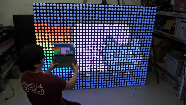
We start this week with very sad news indeed. You may have heard about the horrific fire on the dive boat Conception off Santa Cruz Island last week, which claimed 33 lives. Sadly, we lost one of our own in the tragedy: Dan Garcia, author of the wildly popular FastLED library. Dan, 46, was an Apple engineer who lived in Berkley; his partner Yulia Krashennaya died with him. Our community owes Dan a lot for the work he put into FastLED over the last seven years, as many an addressable LED is being driven by his code today. Maybe this would be a good chance to build a project that uses FastLED and add a little light to the world, courtesy of Dan.
In happier news, the biggest party of the hardware hacking year is rapidly approaching. That’s right, the 2019 Hackaday Superconference will be upon us before you know it. Rumor has it that there aren’t that many tickets left, and we haven’t even announced the slate of talks yet. That’s likely to clean out the remaining stock pretty darn quickly. Are you seriously prepared to miss this? It seems like a big mistake to us, so why don’t you hop over and secure your spot before you’re crying into your Club-Mate and wondering what all the cool kids will be doing in November.
Of course one of the highlights of Superconference is the announcement of the Hackaday Prize winner. And while we naturally think our Prize is the best contest, that doesn’t mean there aren’t others worth entering. MyMiniFactory, the online 3D-printing community, is currently running a “Design with Arduino” competition that should be right up the alley of Hackaday readers. The goal is simple: submit a 3D-printed design that incorporates Arduino or other electronics. That’s it! Entries are accepted through September 16, so you’ve still got plenty of time.
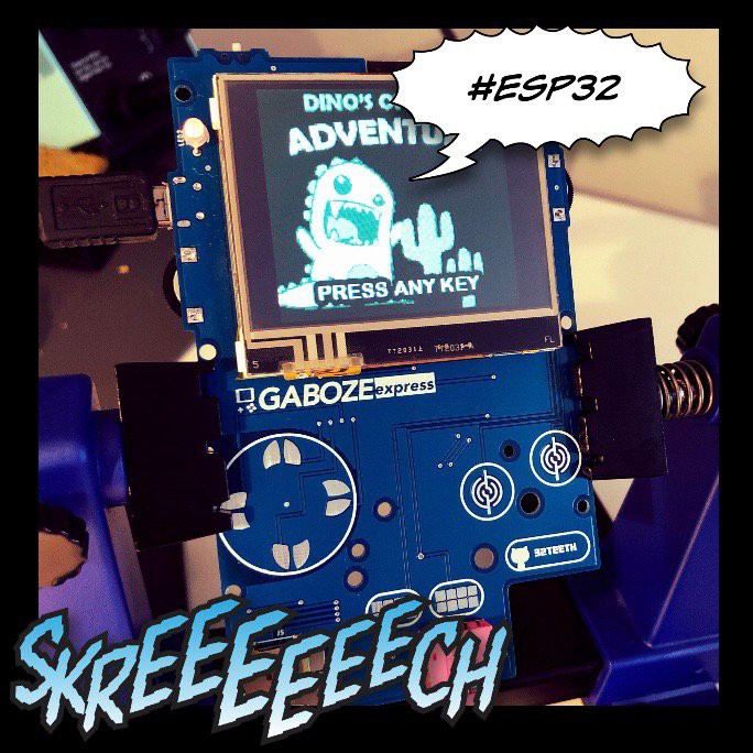
Sometimes you see something that just floors you. Check out this tiny ESP32 board. It doesn’t just plug into a USB port – it fits completely inside a standard USB Type A jack. The four-layer board sports an ESP32, FTDI chip, voltage regulator, an LED and a ceramic antenna for WiFi and Bluetooth. Why would you want such a thing? Why wouldn’t you! The board is coming soon on CrowdSupply, so we hope to see projects using this start showing up in the tipline soon.
Here’s a “why didn’t I think of that?” bench tip that just struck us as brilliant. Ever had to probe a board to trace signal paths? It’s a common enough task for reverse engineering and repairs, but with increasingly dense boards, probing a massive number of traces is just too much of a chore. Hackaday superfriend Mike Harrison from “mikeselectricstuff” makes the chore easier with a brush made from fine stainless wires crimped into a ring terminal. Attached to one probe of a multimeter, the brush covers much more of the board at a time, finding the general area where your trace of interest ends up. Once you’re in the neighborhood you can drop back to probing one pad at a time. Genius! We’d imagine a decent brush could also be made from a bit of coax braid too.
Another shop tip to wrap up this week, this one for woodworkers and metalworkers alike. Raw materials are expensive, and getting the most bang for your buck is often a matter of carefully laying out parts on sheet goods to minimize waste. Doing this manually can be a real test of your spatial relations skills, so why not automate it with this cut list optimizer? The app will overlay parts onto user-defined rectangles and snuggle them together to minimize waste. The program takes any units, can account for material lost to kerfs, and will even respect grain direction if needed. It’s built for wood, but it should prove useful for sheet metal on a plasma cutter, acrylic on a laser, or even PCBs on a panel.