Weather is one of those things that seems to be endlessly interesting to hackers. We may decry the notion that weather can be accurately predicted two days out, much less seven, but if there’s an extended forecast available, by gosh we’re gonna take a gander at it.
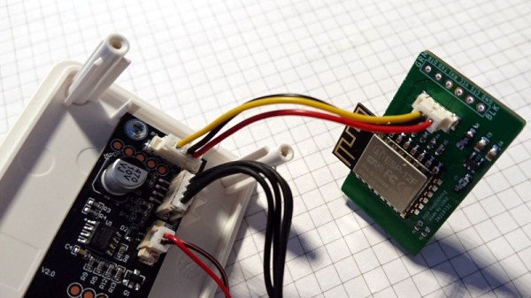
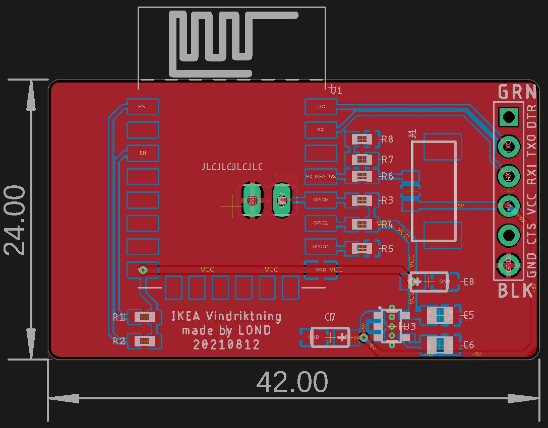
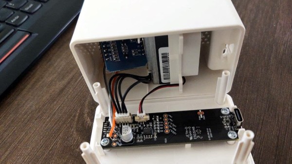
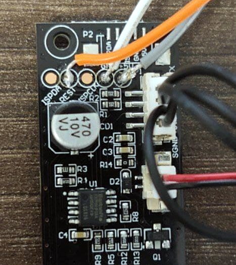
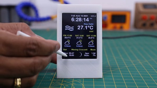
So why pick up your phone or open a browser tab every time you want to check the temperature? If you’re so into it, you should build a desktop weather widget. [opengreenenergy] has written a great guide to a tidy build of this classic and oh-so-useful project that covers everything from the soldering to obtaining an API key. Inside is an ESP8266 and a 2.8″ touch screen display that shows localized conditions via Open Weather Map. The main screen shows the time, date, current weather, 7-day forecast, and the moon phase for each day, and subsequent screens go into further detail. It’s informative without being busy.
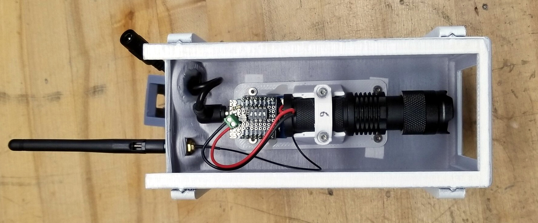
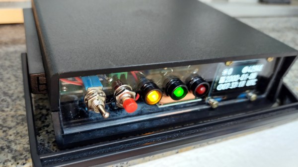
We love the streamlined look of the snap-fit enclosure. This may be a fairly simple project, but the build as designed is challenging due to the space constraints inside. Check out the video after the break, which features the venerable Stickvise.
What? You’ve never heard of the Stickvise? You must be new around here. Allow me to introduce you two.
Continue reading “Nothing Should Cloud The Build Of This Wieldy Weather Widget”