Chart recorders are vintage devices that were used to plot analog values on paper. They’re similar to old seismometers which plot seismic waves from earthquakes. The device has a heated pen which moves across a piece of thermally sensitive paper. This paper is fed through the machine at a specified rate, which gives two dimensions of plotting.
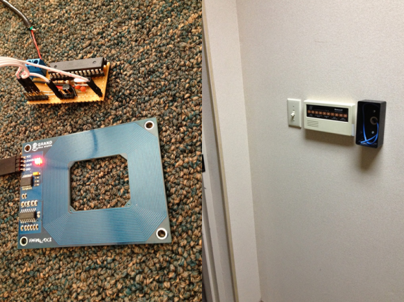
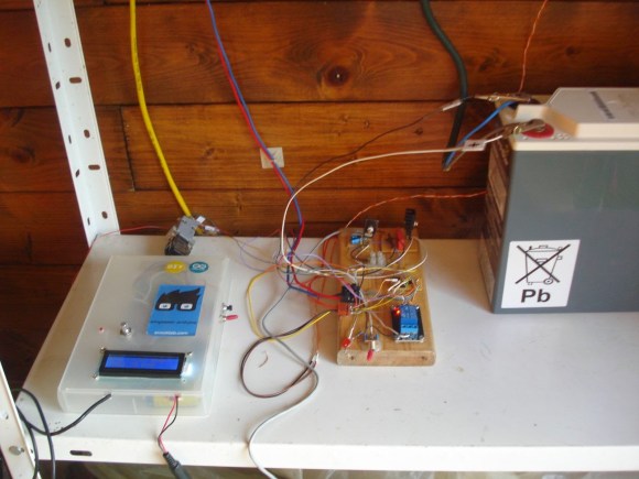
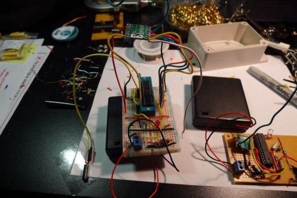
[Marv] ended up getting a couple of discontinued chart recorders and figured out the interface. Five parallel signals control the feed rate of the paper, and an analog voltage controls the pen location. The next logical step was to hook up an Arduino to control the plotter.
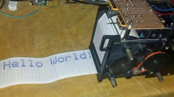
However, once the device could plot analog values, [Marv] quickly looked for a new challenge. He wanted to write characters and bitmaps using the device, but this would require non-continuous lines. By adding a solenoid to lift the pen, he built a chart recorder printer.
After the break, check out a video of the chart recorder doing something it was never intended to do. If you happen to have one of these chart recorders, [Marv] included all of the code in his writeup to help you build your own.
 In the near future, we will all reside in households that contain hundreds of little devices intertwingled together with an easily connectable and controllable network of sensors. For years, projects have been appearing all around the world,