Programming Micros With Impossibly Cheap Bluetooth Adapters

tooth

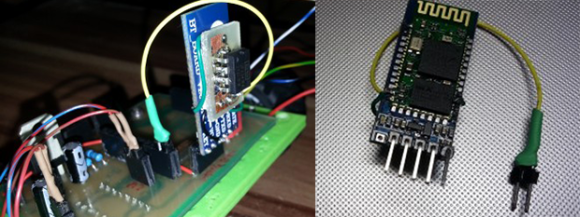
[Zenios] and [Raivis] are building a small balancing robot, and for communications to the outside world, they’re using a small, extremely cheap Bluetooth adapter. They figured uploading code to the microcontroller over Bluetooth would be a good idea, but their adapter, a cheap HC-06 module, had no way of resetting the microcontroller; it just provided Tx and Rx the serial port. They did notice a LED blinked when a device wasn’t connected to the adapter, so with a simple circuit they kludged a reset circuit where it wasn’t intended.

The small LED on the HC-06 module blinks when nothing is connected, and remains on when a connection is established. Figuring a new connection would be a good time to upload new code, the guys needed to design a circuit that would stay low when the LED was blinking, and switch to high when the LED was on.

A simple RC filter took care of the blinking LED, keeping the line low until a device connected. Bringing the logic level high when the LED stayed solid required digging through a part drawer, eventually finding an LM741 p differential amplifier.

After a few small changes to the bootloader, the guys had a reliable means of flashing new firmware without the need of programming adapters or wires draped over their workspace, all with a Bluetooth adapter that shouldn’t have this capability. Video below.

Continue reading “Programming Micros With Impossibly Cheap Bluetooth Adapters”

Upgrade Your Garage Door With Arduino And RFID

RFID Garage Door Opener

[Jason] really wanted to build an RFID controlled garage door opener and decided to turn to Arduino to get the job done. For someone who’s never worked with an Arduino before, he really seemed to know what he was doing.

The Arduino acts as the brains of the operation while an off-the-shelf NFC/RFID reader module is used to read the RFID tags. To add new keys to the system, [Jason] simply swipes his “master” RFID key. An indicator LED lights up and a piezo speaker beeps, letting you know that the system is ready to read a new key. Once the new key is read, the address is stored on an EEPROM. From that point forward the new key is permitted to activate the system.

Whenever a valid key is swiped, the Arduino triggers a relay which can then be used to control just about anything. In this case, [Jason] plans to use it to control his garage door. The system also has a few manual controls. First is the reset button. If this button is held down for two seconds, all of the keys from the EEPROM are erased. This button would obviously only be available to people who are already inside the garage. There is also a DIP switch that allows the user to select how long the relay circuit should remain open. This is configurable in increments of 100ms.

For now the circuit is wired up on a couple of breadboards, but it might be a good idea to use something more permanent. [Jason] could always take it a step further and learn to etch his own PCB’s. Or he could even design a board in Eagle CAD and order a real printed board. Don’t miss the video description of the RFID system below. Continue reading “Upgrade Your Garage Door With Arduino And RFID”

Solderless Noise-o-Tron Kit Makes Noise At Chicago Makerfaire

Noise-o-Tron

Anyone who’s manned a hackerspace booth at an event knows how difficult it can be to describe to people what a hackerspace is. No matter what words you use to describe it, nothing really seems to do it justice. You simply can’t use words to make someone feel that sense of accomplishment and fun that you get when you learn something new and build something that actually works.

[Derek] had this same problem and decided to do something about it. He realized that in order to really share the experience of a hackerspace, he would have to bring a piece of the hackerspace to the people.  That meant getting people to build something simple, but fun. [Derek’s] design had to be easy enough for anyone to put together, and inexpensive enough that it can be produced in moderate quantities without breaking the bank.

[Derek] ended up building a simple “optical theremin”. The heart of this simple circuit is an ATTiny45. Arduino libraries have already been ported to this chip, so all [Derek] had to do was write a few simple lines of code and he was up and running. The chip is connected to a photocell so the pitch will vary with the amount of light that reaches the cell. The user can then change the pitch by moving their hand closer or further away, achieving a similar effect to a theremin.

[Derek] designed a simple “pcb” out of acrylic, with laser cut holes for all of the components. If you don’t have access to a laser cutter to cut the acrylic sheets, you could always build your own. The electronic components are placed into the holes and the leads are simply twisted together. This allows even an inexperienced builder to complete the project in just five to ten minutes with no complicated tools. The end result of his hard work was a crowded booth at a lot of happy new makers. All of [Derek’s] plans are available on github, and he hopes his project will find use at Makerfaires and hackerspace events all over the world.

A Quadcopter From Scratch

Quadcopter

[AwesomeAwesomeness] wanted a low cost quadcopter, so he built one from scratch. Okay, not quite from scratch. [AA’s] cookie mix came in the form of an Arduino Uno and some motors. He started with motors and propellers from a Hubsan X4 quadcopter. Once the power system was specified, [AA] designed a frame, arms, and motor pods in Solidworks. He printed his parts out and had a sweet quadcopter that just needed a brain.

Rather than buy a pre-made control board, [AA] started with an Arduino Uno.  An Arduino alone can’t source enough current to drive the Hubsan motors. To handle this, [AA] added a ULN2003A  Darlington transistor array. The 2003A did work, but [AA] had some glitching issues. We think FETs would do much better in this application, especially when running PWM.

On the control side of things, [AA] added an MPU-6050 Triple Axis Accelerometer and Gyro breakout from SparkFun. The 6050 has 3 gyros and 3 accelerometers in one package. Plenty for a quadcopter.

All this left was the coding. Multicopters generally use Proportional-Integral-Derivative (PID) control loops to maintain stability in the air. [AA] used the Arduino PID library for his quadcopter. He actually created two PID instances – one for pitch and one for roll.

[AA] doesn’t have any videos of his quadcopter in action yet, and we’re guessing this is due in part to weight. Lifting an Uno, a perfboard, and a frame is a tall task for those motors. Going with a one of the many tiny Arduino’s out there would help reduce weight. In addition, [AA] could use a gear system similar to what is used in the Syma X series quadcopters. Stick with it – you’re on the right track!


Hackaday Links: May 11, 2014

hackaday-links-chain

North Korean drones! Yes, your local hobby shop has the same aerial reconnaissance abilities as North Korea. Props to Pyongyang for getting v-tail mixing down.

There’s nothing quite as satisfying as the look of a well laid out resistor array, and the folks at Boldport have taken this to a new level. It’s an art piece, yes, but these would make fabulous drink coasters.

Here’s something even more artistic. [cpurola] found a bunch of cerdip EPROMs and bent the pins in a weird chainmaille-esque way. The end result is an EPROM bracelet, just in time for mother’s day. It’s a better use for these chips than tearing them apart and plundering them for the few cents worth of gold in each.

[John] still uses his original Xbox for xmbc, but he’d like to use the controllers with his computer. He never uses the third and fourth controller ports, so he stuck those in his computer. It’s as simple as soldering the controller port module to a connector and plugging it into an internal USB port. Ubuntu worked great, but Windows required XBCD.

[Kerry] has modified an FT232 USB/UART thingy as an Arduino programmer before. The CP2102 USB/UART is almost as popular on eBay, a little less expensive, and equally suited for ‘duino programming. It requires desoldering a resistor and soldering a jumper on a leadless package, but with a fine solder tip, it’s not too bad.

folding arduino lab

DIY Arduino Cases You Never Knew Existed

There are sure a lot of varieties of Arduinos out there but there may even be more of a variety when it comes to Arduino Cases. Let’s take the most popular Arduino form factor, the Uno. Below are a handful of unique cases for the Uno-sized boards.


by [Megaduty], Arduino Protection Box beefy arduino case

We’ll call this one robust. Although it is 3D printed, its intent is to be extremely protective of the inhabitant. Some extra thought went into this case, no tools are needed! After the Arduino snaps into place, so does the cover. There is an access door to get the input/output wires to the free world. [Megaduty] suggests that this contains $0.10 of plastic. Not a bad deal.


Continue reading “DIY Arduino Cases You Never Knew Existed”

Two Wheeler Is Gyroscope Stabilized

[Jim] loves gyros – not those newfangled MEMS devices, but old-fashioned mechanical gyroscopes. His obsession has pushed him to build this gyro stabilized two wheeler. We love watching hacks come together from simple basic materials and hand tools, with liberal amounts of hot glue to hold everything in place.  That seems to be [Jim’s] philosophy as well.

This is actually the fifth incarnation of [Jim’s] design. Along the way he’s learned a few important secrets about mechanical gyro design, such as balancing the motor and gyro assembly to be just a bit top-heavy. [Jim’s] gyro is a stack of CDs directly mounted to the shaft of a brushed speed400 R/C airplane motor. The motor spins the CDs up at breakneck speed – literally. [Jim] mentions that they’ve exploded during some of his early experiments.

The gyroscope is free to move in the fore-aft direction. Side to side balance tilting is on the wheels themselves. The wheels are model airplane wheels, which have a curved tread. No cheating by using flat LEGO wheels in [Jim’s] lab! A potentiometer measures the tilt angle of the gyro. The voltage from the pot is fed into an Arduino Uno which closes the loop by moving a servo mounted counterweight.

The vehicle is controlled with a regular R/C plane radio. A servo steers the front wheel while another DC motor drives the rear wheel. Not only is [Jim’s] creation able to balance on its own, it can even make a U-Turn within a hallway.

Continue reading “Two Wheeler Is Gyroscope Stabilized”