When you think of DIY hardware, genetic research tools are not something that typically comes to mind. But [Stacey] and [Matt]’s OpenPCR project aims to enable anyone to do polymerase chain reaction (PCR) research on the cheap.
PCR is a process that multiplies a specific piece of DNA a few million times. It can be used for many purposes, including DNA cloning and DNA fingerprinting for forensics. PCR is also used for paternity testing.
The process involves baking the DNA at specific temperatures for the right amount of time. The DNA is first denatured, to split the helix into individual strands. Next, the temperature is lowered and primers are bound to the strands. Finally, another temperature is used to allow the polymerase to duplicate the DNA. This process is repeated to multiply the DNA.
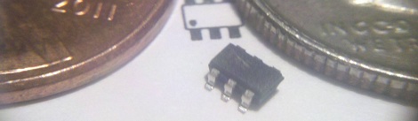
The OpenPCR uses an Arduino to control a solid state relay. This relay provides power to two large resistors that act as heaters. A MAX31855 is used to read a thermocouple over SPI and provide feedback for the system. A computer fan is used to cool the device down.
A milled aluminium sample holder houses and heats the samples during cycling. The laser cut, t-slot construction case features some helix art, and houses all of the components. It will be interesting to see what applications this $85 PCR device can perform.
Via Adafruit