A Brand-New Additive PCB Fab Technique?

Usually when we present a project on these pages, it’s pretty cut and dried — here’s what was done, these are the technologies used, this was the result. But sometimes we run across projects that raise far more questions than they answer, such as with this printed circuit board that’s actually printed rather than made using any of the traditional methods.

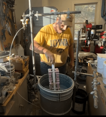
Right up front we’ll admit that this video from [Bad Obsession Motorsport] is long, and what’s more, it’s part of a lengthy series of videos that document the restoration of an Austin Mini GT-Four. We haven’t watched the entire video much less any of the others in the series, so jumping into this in the middle bears some risk. We gather that the instrument cluster in the car is in need of a tune-up, prompting our users to build a PCB to hold all the instruments and indicators. Normally that’s pretty standard stuff, but jumping to the 14:00 minute mark on the video, you’ll see that these blokes took the long way around.

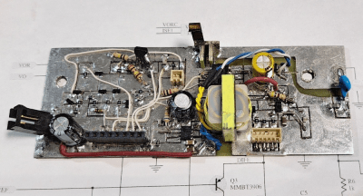
Starting with a naked sheet of FR4 substrate, they drilled out all the holes needed for their PCB layout. Most of these holes were filled with rivets of various sizes, some to accept through-hole leads, others to act as vias to the other side of the board. Fine traces of solder were then applied to the FR4 using a modified CNC mill with the hot-end and extruder of a 3D printer added to the quill. Components were soldered to the board in more or less the typical fashion.

It looks like a brilliant piece of work, but it leaves us with a few questions. We wonder about the mechanics of this; how is the solder adhering to the FR4 well enough to be stable? Especially in a high-vibration environment like a car, it seems like the traces would peel right off the board. Indeed, at one point (27:40) they easily peel the traces back to solder in some SMD LEDs.

Also, how do you solder to solder? They seem to be using a low-temp solder and a higher temperature solder, and getting right in between the melting points. We’re used to seeing solder wet into the copper traces and flow until the joint is complete, but in our experience, without the capillary action of the copper, the surface tension of the molten solder would just form a big blob. They do mention a special “no-flux 96S solder” at 24:20; could that be the secret?

We love the idea of additive PCB manufacturing, and the process is very satisfying to watch. But we’re begging for more detail. Let us know what you think, and if you know anything more about this process, in the comments below.

Continue reading “A Brand-New Additive PCB Fab Technique?”

Fundamentals Of FMCW Radar Help You Understand Your Car’s Point Of View

Pretty much every modern car has some driver assistance feature, such as lane departure and blind-spot warnings, or adaptive cruise control. They’re all pretty cool, and they all depend on the car knowing where it is in space relative to other vehicles, obstacles, and even pedestrians. And they all have another thing in common: tiny radar sensors sprinkled around the car. But how in the world do they work?

If you’ve pondered that question, perhaps after nearly avoiding rear-ending another car, you’ll want to check out [Marshall Bruner]’s excellent series on the fundamentals of FMCW radar. The linked videos below are the first two installments. The first covers the basic concepts of frequency-modulated continuous wave systems, including the advantages they offer over pulsed radar systems. These advantages make them a great choice for compact sensors for the often chaotic automotive environment, as well as tasks like presence sensing and factory automation. The take-home for us was the steep penalty in terms of average output power on traditional pulsed radar systems thanks to the brief time the radar is transmitting. FMCW radars, which transmit and receive simultaneously, don’t suffer from this problem and can therefore be much more compact.

Continue reading “Fundamentals Of FMCW Radar Help You Understand Your Car’s Point Of View”

Building An Automotive Load Dump Tester

For those who have not dealt with the automotive side of electronics before, it comes as somewhat of a shock when you find out just how much extra you have to think about and how tough the testing and acceptance standards are. One particular test requirement is known as the “load dump” test. [Tim Williams] needed to build a device (first article of three) to apply such test conditions and wanted to do it as an exercise using scrap and spares. Following is a proper demonstration of follow-through from an analytical look at the testing specs to some interesting hand construction.

Manhattan-style layout

The load dump test simulates the effect of a spinning automotive alternator in a sudden no-load scenario, such as a loose battery terminal. The sudden reduction in load (since the battery no longer takes charging current) coupled with the inductance of the alternator windings causes a sudden huge voltage spike. The automotive standard ISO 7637-2:2011 dictates how this pulse should be designed and what load the testing device must drive.

The first article covers the required pulse shape and two possible driving techniques. It then dives deep into a case study of the Linear Tech DC1950A load dump tester, which is a tricky circuit to understand, so [Tim] breaks it down into a spice model based around a virtual transistor driving an RC network to emulate the pulse shape and power characteristics and help pin down the specs of the parts needed. The second article deals with analysing and designing a hysteric controller based around a simple current regulator, which controls the current through a power inductor. Roughly speaking, this circuit operates a bit like a buck converter with a catch diode circulating current in a tank LC circuit. A sense resistor in the output path is used to feedback a voltage, which is then used to control the driving pulses to the power MOSFET stage. [Tim] does a good job modeling and explaining some of the details that need to be considered with such a circuit.

Continue reading “Building An Automotive Load Dump Tester”

Junk Bin Build Lets You Test Fuel Injectors On The Cheap

Fiddle around with cars long enough and you’ll realize two things: first, anything beyond the simplest repairs will probably require some kind of specialized tool, and second, those tools can be prohibitively expensive. That doesn’t mean you’re out of luck, though, especially if you’ve got scrap galore and a DIY spirit, as this junk bin fuel injector test stand ably demonstrates.

[Desert Rat Racer]’s test rig is designed to support four injectors at once and to test them under conditions as close as possible to what they’ll experience when installed. To that end, [Rat] mounted a junk intake manifold to a stand made from scrap wood and metal found by the side of the road. A pickle jar serves as a reservoir for the test fluid — he wisely used mineral spirits as a safer substitute for gasoline — and a scrap electric fuel pump pressurizes a junk fuel rail, which distributes fuel to the injectors under test.

For testing, the injectors are wired up to an electric injector tester, which is one of the few off-the-shelf components in the build. The fuel pump and injectors are powered by the 12 volt rail of a scrapped PC power supply. Just being able to watch the spray pattern is often enough to find a faulty injector, but in case a more quantitative test is indicated, each injector is positioned over a cheap glass cylinder to catch the test fluid, and scraps of a tape measure are used to measure the depth of the collected fluid. No fancy — and expensive — graduated cylinders required.

While we truly respect the hackiness of [Desert Rat Racer]’s build, the concept of avoiding buying tactical tools is foreign to us. We understand the logic of not dropping a ton on a single-use tool, but where’s the fancy blow-molded plastic case?

Continue reading “Junk Bin Build Lets You Test Fuel Injectors On The Cheap”

Toyota Heater Switches Learn New Tricks

The look, the feel, the sound — there are few things more satisfying in this world than a nice switch. If you’re putting together a device that you plan on using frequently, outfitting it with high-quality switches is one of those things that’s worth the extra cost and effort.

So we understand completely why [STR-Alorman] went to such great lengths to get the aftermarket seat heaters he purchased working with the gorgeous switches Toyota used in the 2006 4Runner. That might not sound like the kind of thing that would involve reverse engineering hardware, creating a custom PCB, or writing a bit of code to tie it all together. But of course, when working on even a halfway modern automobile, it seems nothing is ever easy.

The process started with opening up the original Toyota switches and figuring out how they work. The six-pin units have a lot going on internally, with a toggle, a rheostat, and multiple lights packed into each one. Toyota has some pretty good documentation, but it still took some practical testing to distill it down into something a bit more manageable. The resulting KiCad symbol for the switch helps explain what’s happening inside, and [STR-Alorman] has provided a chart that attributes each detent on the knob with the measured resistance.

But understanding how the switches worked was only half the battle. The aftermarket seat heaters were only designed to work with simple toggles, so [STR-Alorman] had to develop a controller that could interface with the Toyota switches and convince the heaters to produce the desired result. The custom PCB hosts a Teensy 3.2 that reads the information from both the left and right seat switches, and uses that to control a pair of beefy MOSFETs. An interesting note here is the use of very slow pulse-width modulation (PWM) used to flip the state of the MOSFET due to the thermal inertia of the heater modules.

We love the effort [STR-Alorman] put into documenting this project, going as far as providing the Toyota part numbers for the switches and the appropriate center-console panel with the appropriate openings to accept them. It’s an excellent resource if you happen to own a 4Runner from this era, and a fascinating read for the rest of us.

Tech In Plain Sight: Windshield Frit

You probably see a frit every day and don’t even notice it. What is it? You know the black band around your car’s windshield? That’s a frit (which, by the way, can also mean ingredients used in making glass) or, sometimes, a frit band. What’s more, it probably fades out using a series of dots like a halftone image, right? Think that’s just for aesthetics? Think again.

Older windshields were not always attached firmly, leading to them popping out in accidents. At some point, though, the industry moved to polyurethane adhesives, which are superior when applied correctly. However, they often degrade from exposure to UV. That’s a problem with a windshield, which usually gets plenty of sunlight.

The answer is the frit, a ceramic-based baked-on enamel applied to both sides of the windshield’s edges, usually using silk screening. The inner part serves as a bonding point for the adhesive. However, the outer part blocks UV radiation from reaching the adhesive. Of course, it also hides the adhesive and any edges or wiring beneath it, too.

Continue reading “Tech In Plain Sight: Windshield Frit”

Ask Hackaday: What’s Your “Tactical Tool” Threshold?

With few exceptions, every field has a pretty modest set of tools that would be considered the minimum for getting most jobs done. A carpenter can make do with tools that would fit in a smallish bag, while a mechanic can handle quite a few repairs with a simple set of socket wrenches and other tools. Even in electronics, a lot of repairs and projects can be tackled with little more than a couple of pairs of pliers, some cutters, and a cheap soldering iron.

But while the basic kit of tools for any job may be enough, there will always be those jobs that need more tools. Oh sure, sometimes you can — and should — make do with what you’ve got; I can’t count the number of times I’ve used an elastic band wrapped around the handles of a pair of needlenose pliers as an impromptu circuit board vise. But eventually, you’re going to come upon a situation where only the “real” tool will do, and substitutes need not apply.

As I look around my shop and my garage, I realize that I may have a problem with these “tactical tool” purchases. I’ve bought so many tools that I’ve used far fewer times than I thought I would, or perhaps even never used, that I’m beginning to wonder if I tackle projects just as an excuse to buy tools. Then again, some of my tactical purchases have ended up being far more useful than I ever intended, which has only reinforced my tendency toward tool collecting. So I thought I’d share a few of my experiences with tactical tools, and see how the community justifies tactical tool acquisitions.

Continue reading “Ask Hackaday: What’s Your “Tactical Tool” Threshold?”