DIY Breadboard Modules For Easy Prototyping

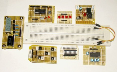
[Rajendra] got tired of building the same basic circuits time and again on the breadboard. He decided to build some simple, modular circuits on protoboard and make them easy to interface with the breadboard. As you can see, he ended up with seven modules that make prototyping faster and easier.

At first glance some might not seem all that beneficial. For instance, making a board for an 18-pin PIC microcontroller into a single-in-line form factor would seem like you’re actually wasting breadboard space when compared to the DIL package of the chip. But consider that the oscillator and its capacitors, reset button, and programming header are also on the breakout board and will not have to be built in place. There are also several I/O boards, one with five buttons, another with an LED bar graph, and a set of LEDs with a SIL resistor package on-board. These modules can be plugged into a breadboard and wired up with jumper wires, or connected directly to the same rows as the microcontroller module.

Making A 3D Printer Work Wirelessly

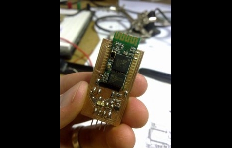
Looking for more ways to enhance his 3D printer, [JJ] decided to make it wireless. He got his hands on some $10 Bluetooth modules and figured this would be just the thing to make the link with his laptop.

They came as surface mount modules, so the first thing he had to do was develop a breakout board that he could patch into his Ultimaker 3D printer. This provided a nice opportunity as he needed to do some level converting to make the 3.3V module play nicely with his 5V CNC electronics. The first version of the board turned out well but he had really a poor communications range. The second version, which is pictured above, hangs the module’s antenna off the edge of the breakout board and works a lot better.

We’ve embedded a clip after the break that walks through the development of this board. [JJ] shared the Eagle CAD files as a megaupload link, but we’ve also mirrored the file after the break for your convenience.

Continue reading “Making A 3D Printer Work Wirelessly”

Cutting Out Your Own Breakout Boards

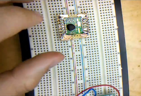
[Caleb] needed to use some surface mount components when prototyping. Instead of buy a breakout board he made one himself without doing any etching. The process he shows off in the video after the break uses copper tape to layout the traces for the board. It’s quite an interesting method which requires a sharp knife and a steady hand.

He used regular protoboard as a substrate and applied a layer of copper tape on the side without copper pads. From there he poked holes for the DIP pin headers. Now it’s time to do some cutting. [Caleb] removed the band of copper that would fall in between the pins of the surface mount device. He then tackedĀ it in place with one dot of solder and drew the traces from the part to the pin headers. After removing the part he cut out the waste in between each line he drew with marker. What he’s left with is a set of thin traces that connect each pin of the surface mount component to the corresponding through-hole pin header.

This is very time-consuming, but then again so is soldering jumper wires to small-pitch components.

Continue reading “Cutting Out Your Own Breakout Boards”

Surface Mount Breakout Boards

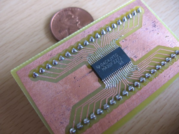
We got a hold of some DS3232 RTC chips in a 20-pin SOIC package. We’d like to have one that is breadboard compatible for easy prototyping but when we searched for SOIC20W breakout board artwork we found none. We used Eagle to design our own and you can see the finished product above which we made using the toner transfer method and cupric chloride.

You’ll find the artwork after the break in case you need to make your own breakout board some day. If you know of surface mount breakout board artwork that is freely available please leave the link in the comments for future use, or send it to us on our tips line and we’ll add it to the post.

Incidentally, the DS3232 is the same as the DS3231 used in the ChronoDot but with the addition of some SRAM. We’ll let you know if we come up with an interesting project for it.

Update: We added 28 SSOP to DIP artwork submitted by [Paul Dekker]

Continue reading “Surface Mount Breakout Boards”

Business Card AVR Board Updated

bcard

Evil Mad Scientist Laboratories has updated their business card AVR breakout boards to version 1.1. We suspect the changes will probably make them even more popular. The boards are designed for the ATmegaXX8 family of microcontrollers. The center has all 28 pins labeled while either end has a prototyping area. An in-system programming header is also provided. For the new version, both prototyping areas have been increased to accommodate DIP14 packages. The holes for the microcontroller are now larger so that they can hold a ZIF socket. Finally, the power and ground traces have been expanded. We’ve always like the versatility of these boards, as demonstrated in the Tennis for Two project, and can’t help wondering if these updates were made to facilitate another project.