VGA, DVI, and HDMI ports use Display Data Channel (DDC) to communicate with connected displays. This allows displays to be plug and play. However, DDC is based on I2C, which is used in all kinds of electronics. To take advantage of this I2C port on nearly every computer, [Josef] built a VGA to I2C breakout.
This breakout is based on an older article about building a $0.25 I2C adapter. This adapter hijacks specific lines from the video port, and convinces the kernel it’s a standard I2C device. Once this is done, applications such as i2c-tools can be used to interact with the port.
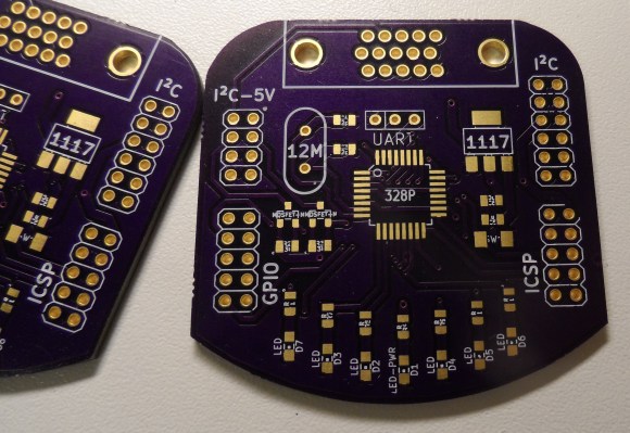
[Josef] decided to go for overkill with this project. By putting an ATmega328 on the board, control for GPIOs and LEDs could be added. Level shifters for I2C were added so it can be used with lower voltage devices. The end product is an I2C adapter, GPIOs, and LEDs that can be controlled directly from the Linux kernel through an unused video port.