Building A Wavetable Synth

Every semester at one of [Bruce Land]’s electronics labs at Cornell, students team up, and pitch a few ideas on what they’d like to build for the final project. Invariably, the students will pick what they think is cool. The only thing we know about [Ian], [Joval] and [Balazs] is that one of them is a synth head. How do we know this? They built a programmable, sequenced, wavetable synthesizer for their final project in ECE4760.

First things first — what’s a wavetable synthesizer? It’s not adding, subtracting, and modulating sine, triangle, and square waves. That, we assume, is the domain of the analog senior lab. A wavetable synth isn’t a deep application of a weird reverse FFT — that’s FM synthesis. Wavetable synthesis is simply playing a single waveform — one arbitrary wave — at different speeds. It was popular in the 80s and 90s, so it makes for a great application of modern microcontrollers.

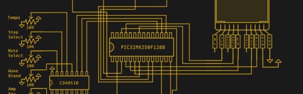
The difficult part of the build was, of course, getting waveforms out of a microcontroller, mixing them, and modulating them. This is a lab course, so a few of the techniques learned earlier in the semester when playing with DTMF tones came in very useful. The microcontroller used in the project is a PIC32, and does all the arithmetic in 32-bit fixed point. Even though the final audio output is at 12-bit resolution, the difference between doing the math at 16-bit and 32-bit was obvious.

A synthesizer isn’t useful unless it has a user interface of some kind, and for this the guys turned to a small TFT display, a few pots, and a couple of buttons. This is a complete GUI to set all the parameters, waveforms, tempo, and notes played by the sequencer. From the video of the project (below), this thing sounds pretty good for a machine that generates bleeps and bloops.

Continue reading “Building A Wavetable Synth”

Motorized Camera Dolly Rolls With The Changes

Over the last semester, Cornell student [Ope Oladipo] had the chance to combine two of his passions: engineering and photography. He and teammates [Sacheth Hegde] and [Jason Zhang] used their time in [Bruce Land]’s class to build a motorized camera dolly for shooting time-lapse sequences.

The camera, in this case the one from an iPhone 6, is mounted to an off-the-shelf robot chassis that tools around on a pair of DC motors. The camera mount uses a stepper motor to get just the right shot. A PIC32 on board the ‘bot takes Bluetooth commands from an iOS app that the team built. The dolly works two ways: it can be controlled manually in free mode, or it can follow a predetermined path at a set speed for a specified time in programmed mode.

Our favorite part of the build? The camera’s view is fed to a smart watch where [Ope] and his team can take still pictures using the watch-side interface. Check it out after the break, and stick around for a short time-lapse demo. We’ve featured a couple of dolly builds over the years. Here’s a more traditional dolly that rides a pair of malleable tubes.

Continue reading “Motorized Camera Dolly Rolls With The Changes”

This Bike Sonar Is Off The Chain

On paper, bicycling is an excellent form of transportation. Not only are there some obvious health benefits, the impact on the environment is much less than anything not directly powered by a human. But let’s face it: riding a bike can be quite scary in practice, especially along the same roads as cars and trucks. It’s hard to analyze the possible threats looming behind you without a pair of eyes in the back of your head.

radar-sweep-display[Claire Chen] and [Mark Zhao] have come up with the next best thing—bike sonar. It’s a two-part system that takes information from an ultrasonic rangefinder and uses it to create sound-localized pings in a rider’s ears. The rangefinder is attached to a servo mounted on the seat post. It sweeps back and forth to detect objects within 4 meters, and this information is displayed radar-sweep-style graphic on a TFT screen via a PIC32.

Though the graphic display looks awesome, it’s slow feedback and a bit dangerous to have to look down all the time — the audio feedback is by far the most useful. The bike-side circuits sends angle and distance data over 2.4GHz to another PIC mounted on a helmet. This PIC uses sound localization to create a ping noise that matches the distance and location of whatever is on your tail. The ping volume is relative to the distance of the object, and you just plug headphones into the audio jack to hear them. Bunny-hop your way past the break to check it out.

Continue reading “This Bike Sonar Is Off The Chain”

Old fashioned polygraph

Retro-Style DIY Polygraph: Believe It Or Not

A polygraph is commonly known as a lie detector but it’s really just a machine with a number of sensors that measure things like heart rate, breathing rate, galvanic skin response and blood pressure while you’re being asked questions. Sessions can be three hours long and the results are examined by a trained polygraph examiner who decides if a measured reaction is due to deception or something else entirely. Modern polygraphs feed data into a computer which analyses the data in real-time.

Cornell University students [Joyce Cao] and [Daria Efimov] decided to try their hand at a more old fashioned polygraph that measures heart and breathing rates and charts the resulting traces on a moving strip of paper as well as a color TFT display. They had planned on measuring perspiration too but didn’t have time. To measure heart rate, electrodes were attached to the test subject’s wrists. To measure breathing they connected a stretch sensor in the form of a conductive rubber cord around three inches long to a shoelace and wrapped this around the test subject’s abdomen.

While the output doesn’t go into a computer for mathematical analysis, it does go to a PIC32 for processing and for controlling the servos for drawing the traces on the paper as well as displaying on the TFT. The circuit between the breathing sensor and the PIC32 is fairly simple, but the output of the heart rate electrodes needed amplification. For that they came up with a circuit based off another project that had a differential amplifier and two op-amps for filtering.

Since parts of the circuit are attached to the body they made some effort to prevent any chance of electrocution. They used 12 volts, did not connect the test subject to power supply chassis ground, and tested the heart rate electrodes with a function generator first. They also included DC isolation circuitry in the form of some resistors and capacitors between the heart rate electrodes and the amplifier circuit. You can see these circuits, as well as a demonstration in the video below. The heart rate output looks a little erratic, no surprise given that the body produces a lot of noise, but the breathing trace looks very clear.

Continue reading “Retro-Style DIY Polygraph: Believe It Or Not”

Move A Robotic Hand With Your Nerve Impulses

Many of us will have seen robotics or prosthetics operated by the electrical impulses detected from a person’s nerves, or their brain. In one form or another they are a staple of both mass-market technology news coverage and science fiction.

The point the TV journalists and the sci-fi authors fail to address though is this: how does it work? On a simple level they might say that the signal from an individual nerve is picked up just as though it were a wire in a loom, and sent to the prosthetic. But that’s a for-the-children explanation which is rather evidently not possible with a few electrodes on the skin. How do they really do it?

A project from [Bruce Land]’s Cornell University students [Michael Haidar], [Jason Hwang], and [Srikrishnaa Vadivel] seeks to answer that question. They’ve built an interface that allows them to control a robotic hand using signals gathered from electrodes placed on their forearms. And their write-up is a fascinating read, for within that project lie a multitude of challenges, of which the hand itself is only a minor one that they solved with an off-the-shelf kit.

The interface itself had to solve the problem of picking up the extremely weak nerve impulses while simultaneously avoiding interference from mains hum and fluorescent lights. They go into detail about their filter design, and their use of isolated power supplies to reduce this noise as much as possible.

Even with the perfect interface though they still have to train their software to identify different finger movements. Plotting the readings from their two electrodes as axes of a graph, they were able to map graph regions corresponding to individual muscles. Finally, the answer that displaces the for-the-children explanation.

There are several videos linked from their write-up, but the one we’re leaving you with below is a test performed in a low-noise environment. They found their lab had so much noise that they couldn’t reliably demonstrate all fingers moving, and we think it would be unfair to show you anything but their most successful demo. But it’s also worth remembering how hard it was to get there.

Continue reading “Move A Robotic Hand With Your Nerve Impulses”

Sorting Resistors With 3D Printing And A PIC

If you aren’t old enough to remember programming FORTRAN on punched cards, you might be surprised that while a standard card had 80 characters, FORTRAN programs only used 72 characters per card. The reason for this was simple: keypunches could automatically put a sequence number in the last 8 characters. Why do you care? If you drop your box of cards walking across the quad, you can use a machine to sort on those last 8 characters and put the deck back in the right order.

These days, that’s not a real problem. However, we have spilled one of those little parts boxes — you know the ones with the little trays. We aren’t likely to separate out the resistors again. Instead, we’ll just treasure hunt for the value we want when we need one.

[Brian Gross], [Nathan Lambert], and [Alex Parkhurst] are a bit more industrious. For their final project in [Bruce Land’s] class at Cornell, they built a 3D-printed resistor sorting machine. A PIC processor feeds a resistor from a hopper, measures it, and places it in the correct bin, based on its value. Who doesn’t want that? You can see a video demonstration, below.

Continue reading “Sorting Resistors With 3D Printing And A PIC”

Recreating Chiptunes In Verilog

The semester is wrapping up at Cornell, and that means it’s time for the final projects from [Bruce Land]’s lab. Every year we see some very cool projects, and this year is no exception. For their project, [Andre] and [Scott] implemented the audio processing unit (APU) of the Nintendo Entertainment System (NES). This is the classic chiptune sound that regaled a generation with 8-bit sounds that aren’t really eight bits, with the help of a 6502 CPU that isn’t really a 6502 CPU.

Unlike the contemporaneous MOS 6581 SID, which is basically an analog synthesizer on a chip, the APU in the NES is extraordinarily spartan. There are two pulse wave channels, a triangle wave channel, a random noise channel, and the very rarely used delta modulation channel (DMC) used to play very low quality audio samples. This is a re-implementation of the NES APU for a university lab; it is very understandable that [Andre] and [Scott] didn’t implement the rarely used DMC.

Everything about the circuitry of the NES is well documented, so [Andre] and [Scott] had a great wiki for their research. At the highest level, the APU runs on a 894kHz clock and controls three channels through dedicated registers. These outputs are fed through a mixer, which the guys scaled and combined into a 16-bit output played through a Wolfson WM8731 audio codec.

After implementing the NES APU, [Andre] and [Scott] added an SD card reader that can read the Nintendo Sound Format – the standard distribution format for NES chiptunes – and emulated a 6502 to control the registers. The result is a relatively simple device that plays NES chiptunes with amazing accuracy. The sound files on the project report sound like the real thing, but this is entirely emulated on modern hardware.