Numerous Quiz Buttons Built On The Cheap

[Sprite_TM] was tapped to build a rather large quiz buzzer system. Judging from his past work we’re not surprised that he seemed to have no trouble fulfilling the request. As the system is not likely to be used again (or rarely if it is) he found a way to finish the project that was both quick and inexpensive.

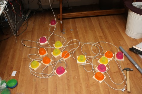
Each buzzer consists of a base, a button (both mechanical and electrical), and a couple of LEDs to indicate who buzzed in first. The mechanical part of the button uses a plastic bowl from Ikea and a wooden dowel surrounded by some pipe insulation. A momentary push switch is glued on the top of that dowel, and the insulation projects above that just a bit. This way it acts as a spring. The Dowel has been sized so that the bowl lip will hit the wooden base just as it clicks the switch.

As you can see, all of the buzzers are interlinked using Ethernet cable. The real trick here is how to read 14 buttons using just one CAT5 cable. This is done with the clever use of a 4×4 button matrix for a total of 16 buttons. The matrix also includes the LEDs for each buzzer. Since CAT5 has four twisted pairs this works out perfectly.

Looking for a more robust system thank this? Here’s a pretty nice one.

Buzzer Project For Classroom Team Games

Want to host a Jeopardy tournament with your friends? Looking to add a bit more fairness to your school’s knowledge bowl? Perhaps you should build some buzz-in hardware of your own.

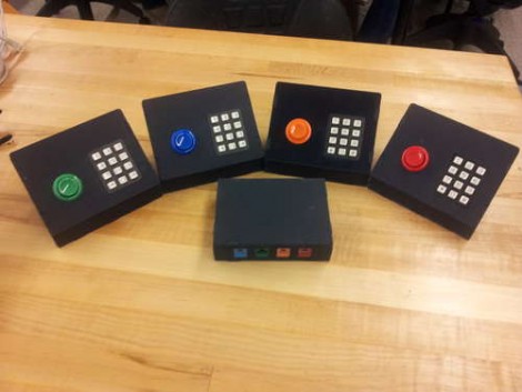
Here you can see [Matt Hanson’s] take on this idea. He used one Arduino to gather not just buzzer info, but also keypad data from four satellite controllers. Each has an RJ45 jack, allowing it to connect tot he base unit with an Ethernet patch cable. We like the color coding that [Matt] chose, which matches the color of the arcade button to the keystone jack on the base. And of course the fantastic look of the water-jet cut cases isn’t lost on us either.

You may wonder why he included a key pad on each controller? It looks like he and a few others worked together to develop a team-based math game for use in school.

Laser Tripwire Alarm System Uses Mirrors To Increase Coverage

laser_tripwire_alarm

Instructables user [EngineeringShock] has been hard at work building a laser trip wire security system, complete with a combination lock. The security system works just like you see in the movies, employing an array of mirrors to bounce the laser across an opening several times in order to secure the space.

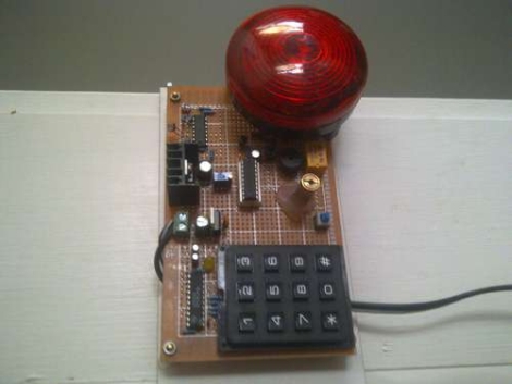
A PIC18F1220 micro controller sits at the center of the alarm and handles the majority of its functions. It takes input from the laser detection circuit, triggers the buzzer, as well as arms and disarms the entire alarm system. An LS7222 digital lock handles the passcode verification side of things, taking input from a 16-button matrix keypad, and telling the PIC when the proper code has been entered.

As you can see in the video below, the alarm system works and the buzzer is quite loud. There is one small problem however – the alarm only arms itself after the proper code has been entered and the lights have been turned off. The light sensing circuit he uses is too sensitive and can only operate in darkness, though he discusses the ability to add a more accurate sensing solution.

If you are interested in reading more about laser tripwire security systems, check out this similar passcode-based system, this alarm system built into a toy, and this Arduino-based alarm system.

Continue reading “Laser Tripwire Alarm System Uses Mirrors To Increase Coverage”

Out Engineering A Sneaky Cat

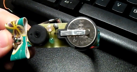
Cats do what they want, which rarely coincides with what their owner wants them to do. In [Dumitru]’s case, his girlfriend’s cat [Pufu] tended to make it outside into the cold more often than desired. Rather than settle with the normal bell which gets obnoxious even when the cat isn’t misbehaving, he decided to put together a custom Cat Finding collar. He used a PIC microcontroller as the brains, and temperature and light sensors to decide whether the cat had snuck into the cold, dark night. Once the cat has been marked as being outside, a buzzer and LED are set to go off at regular intervals until returned into the safety of the indoors.

[Dumitru]’s website along with his YouTube videos are in Romanian, though the schematics and source code provided speak for themselves. He does a wonderful job walking through the entire design process, including time spend in the IDE as well as EAGLE designing the board. YouTube has managed to subtitle the majority of the details, but we imagine this post will be a real treat to any Romanian speaking hobbyists out there. Be sure to catch both videos after the break.

Continue reading “Out Engineering A Sneaky Cat”

Tiny Optical Theremins


Matrixsynth pointed out a couple incredibly small optical theremins that look like they’d make for a great afternoon project. [AlexArt] first built the simple circuit on a piece of protoboard (Google translated). Knowing he could go smaller, he then built it freeform with a buzzer instead of a full size speaker. The design is based around the common 555 chip and photoresistor. Here’s a simple circuit you can use to lay out your own. The optical theremin should not be confused with the traditional RF theremin since the name comes from the similar sound, not similar construction.