If you need a very thin, low power display that doesn’t use a whole bunch of pins on your microcontroller, [bobricius] has just the thing for you. His entry to the Hackaday Prize this year is a Charlieplexed LED display. With this board, you can drive 110 LEDs using only 11 GPIO pins.
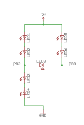
Charlieplexing is a bit of a dark art around these parts. That’s not to say the theory is difficult; it’s really just sourcing or sinking current from a GPIO pin and arranging LEDs unparallel to each other. The theory is one thing, implementation is another. To build a Charlieplexed LED matrix, you need to go a bit crazy with the PCB layout, and god help you if you’re doing this point-to-point on a perf board.
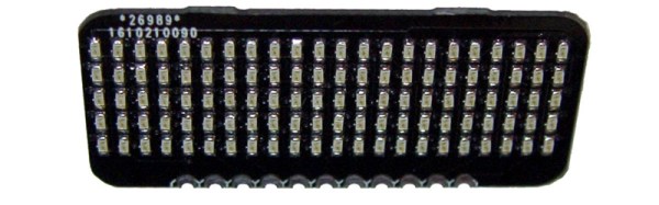
Somehow, [bobricius] managed to fit 110 LEDs on a PCB, all while managing to break out those signal wires to a sensible set of pads on one side of the board. Only eleven pins are required to drive all these LEDs, making this project a great foundation for some very cool wearables or other projects that require a bright, low-res display.
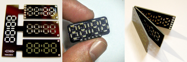
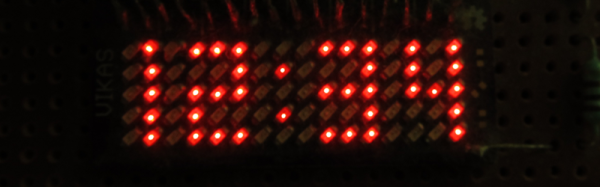
Since [bobricius] can put 110 LEDs on a small board, he can obviously take LEDs away from that board. That’s what he did with his cut down version designed to be a clock. Both are great little boards, and the perfect solution for tiny displays for low-pin-count micros.
Continue reading “Hackaday Prize Entry: Micro Matrix Charlieplexed Displays”