Home Built PCB Mill Reportedly Doesn’t Suck

It’s 2017, and getting a PCB professionally made is cheaper and easier than ever. However, unless you’re lucky enough to be in Shenzhen, you might find it difficult to get them quickly, due to the vagaries of international shipping. Whether you want to iterate quickly on designs, or just have the convenience of speed, it can be useful to be able to make your own PCBs at home. [Timo Birnschein] had just such a desire and set about building a PCB mill that doesn’t suck.

It might sound obvious, but it bears thinking about — if you know you’re incapable of building a good PCB mill in a reasonable period of time, you might save yourself a lot of pain and lost weekends by just ordering PCBs elsewhere. [Timo] was fairly confident however that the build would be able to churn out some usable boards, however, and got to work.

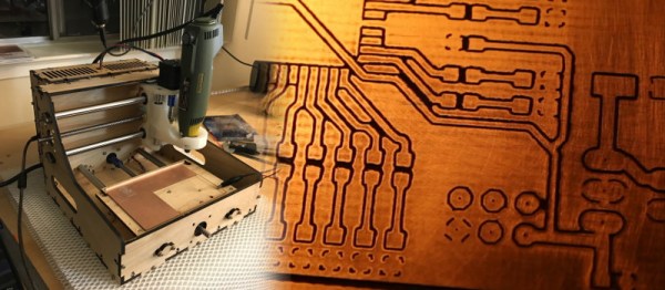
The build is meant to be accessible to the average hacker who wants one. The laser cut & 3D printed parts are readily available these days thanks to online services that can manufacture for those who don’t have the machines at home. [Timo] uses a rotary multitool for a spindle, a common choice for a budget CNC build.

With the hardware complete, [Timo] has spent time working on optimising the software side of things. Through careful optimisation of the G-Code, [Timo] has been able to improve performance and reduce stress on the tooling. It’s not enough to just build a good mill — you’ve got to have your G-Code squared away as well.

Overall, the results speak for themselves. The boards don’t suck; the mill can do traces down to 8 mil, and even drill the holes. We’d love to have one on the workbench when busting out some quick prototypes. For another take on the home-built PCB mill, why not check out this snap-together version?

Zeroing CNC Mills With OpenCV

For [Jay] and [Ricardo]’s final project for [Dr. Bruce Land]’s ECE4760 course at Cornell, they tackled a problem that is the bane of all machinists. Their project finds the XY zero of a part in a CNC machine using computer vision, vastly reducing the time it take to set up a workpiece and giving us yet another reason to water down the phrase ‘Internet of Things’ by calling this the Internet of CNC Machines.

For the hardware, [Jay] and [Ricardo] used a PIC32 to interface with an Arducam module, a WiFi module, and an inductive sensor for measuring the distance to the workpiece. All of this was brought together on a PCB specifically designed to be single-sided (smart!), and tucked away in an enclosure that can be easily attached to the spindle of a CNC mill. This contraption looks down on a workpiece and uses OpenCV to find the center of a hole in a fixture. When the center is found, the mill is zeroed on its XY axis.

The software is a bit simpler than a device that has OpenCV processing running on a microcontroller. Detecting the center of the bore, for instance, happens on a laptop running a few Python scripts. The mill attachment communicates with the laptop over WiFi, and sends a few images of the downward-facing camera over to the laptop. From there, the laptop detects the center of the bore in the fixture plate and generates some G-code to send over to the mill.

While the device works remarkably well, and is able to center the mill fairly quickly and without a lot of user intervention, there were a few problems. The camera is not perfectly aligned with the axis of the spindle, making the math harder than it should be. Also, the enclosure isn’t rated for being an environment where coolant is sprayed everywhere. Those are small quibbles, and these problems could be fixed simply by designing and printing another enclosure. The device works, though, and really cuts down on the time it takes to zero out a mill.

You can check out the video description of the build below.

Continue reading “Zeroing CNC Mills With OpenCV”

Hackaday Prize Entry: DIY Automatic Tool Changer

Choosing between manually changing endmill bits on a CNC machine and investing in an expensive automated solution? Not for [Frank Herrmann], who invented the XATC, an eXtremely simple Automated Tool Changer. [Frank’s] ingenious hack achieves the same functionality as an industrial tool changer using only cheap standard hardware you might have lying around the workshop.

xatc_carouselLike many ATCs, this one features a tool carousel. The carousel, which is not motorized, stores each milling bit in the center bore of a Gator Grip wrench tool. To change a tool, a fork wrench, actuated by an RC servo, blocks the spindle shaft, just like you would do it to manually change a tool. The machine then positions the current bit in an empty Gator Grip on the carousel and loosens the collet by performing a circular “magic move” around the carousel. This move utilizes the carousel as a wrench to unscrew the collet. A short reverse spin of the spindle takes care of the rest. It then picks another tool from the carousel and does the whole trick in reverse.

The servo is controlled via a WiFi connected NodeMCU board, which accepts commands from his CNC controller over HTTP. The custom tool change sequences are provided by a few JavaScript macros written for the TinyG workspace on chilipeppr.com, a browser-based G-code host. Enjoy the video of [Frank Herrmann] explaining his build!

Thanks to Smoothieboard creator [Arthur Wolf], who is currently working on a similar project, for the tip!

The HackadayPrize2016 is Sponsored by:

CNC Clock Mills Itself, Displays The Time

[Christian] wrote and sells some CAM/CNC controller software. We’re kinda sticklers for open source, and this software doesn’t seem to be, so “meh”. But what we do like is the Easter egg that comes included: the paths to mill out the base for a clock, and then the codes to move steel ball-bearings around to display the time.

Of course we’d like to see more info (more, MORE, MOAR!) but it looks easy enough to recreate. We could see redesigning this with marbles and a vacuum system, for instance. The seats for the ball bearings don’t even need to be milled out spheres. You could do this part with a drill press. Who’s going to rebuild this for their 3D printer? You just have to make sure that the machine is fast enough to move the balls around within one minute.

Continue reading “CNC Clock Mills Itself, Displays The Time”

3D Scanned, CNC-Milled, Pumpkin Selfie

When you have a CNC mill sitting around, it almost seems anachronistic to pull out a kitchen knife to carve a pumpkin. You can hardly blame [Nathan Bentall] for choosing an endmill instead. If you’re feeling the same, check out his blog post where [Nathan] works through all the steps involved in going from a raw pumpkin to a 3D RGB LED bust of himself. To put his head on the pumpkin’s shoulders he captured a depth map using a Kinect and then got down to some unorthodox milling.

Continue reading “3D Scanned, CNC-Milled, Pumpkin Selfie”

Desktop CNC From Hardware Parts Really Makes The Cut

We love shop made CNC mills, so when [joekutz] tipped us off about the desktop sized CNC he just completed, we had to take a look. Each axis slides around on ball bearing drawer slides, and the machine itself is constructed with MDF and aluminum. And the results it produces are fantastic.

4950561437395360713thumb
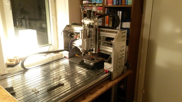
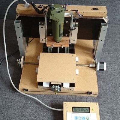
The machine’s work area weighs in at 160*160mm with a height of 25mm. Its the table is moved around with a pair of NEMA17 motors and M8 stainless steel threaded rods. Motor control is done with a pair of Arduino’s but they also do double duty with one processing G-code while the other handles the keypad and LCD interface.

The business end is a Proxxon rotary tool whizzing up to 2000RPM, and while [joekutz] hasn’t tried it on soft metals like brass or aluminum, he has successfully cut and engraved wood, plastics and copper clad PCB material.

Be sure to join us after the break for some YouTube videos. [joe] has posted three of a planned five-part-series which aren’t linked to in the project page shown above. to see this machine in action and get a rundown how it all works

Continue reading “Desktop CNC From Hardware Parts Really Makes The Cut”

Tumblemill

The Tumblemill: Homemade CNC Milling

[Jens] aka [Tumblebeer] has compiled an impressive overview of the Tumblemill, his homemade CNC mill. It warms our hearts to learn that [Tumblebeer] was inspired to pursue electronics by projects featured here on Hackaday, even if it means he dropped out of med school to pursue electrical engineering. We’re glad he’s following his passion, though, and reading through his blog reveals just how far he’s come: from fiery disaster in his first projects to a gradual obsession with making a CNC device, [Tumblebeer] has made plenty of mistakes along the way, but that’s how it should be.

His first iteration was a CNC router that used rubber wheels as linear bearings. It worked…barely. His latest build grew out of meticulous Solidworks modelling, with a moving gantry design constructed largely from aluminum, and upgraded linear motion: this time a bit overkill, using HIWIN HGH20CA blocks. Rather than sourcing a traditional spindle mount, [Tumblebeer] opted for the housing from a LM50UU bearing, which provided both the perfect fit and a sturdier housing for his 2.2kw spindle.

Visit his project blog for the details behind the mill’s construction, including a lengthy installment of upgrades, and hang around for a demo video below, along with the obligatory (and always appreciated) inclusion of the Jolly Wrencher via defacing an Arduino.

Continue reading “The Tumblemill: Homemade CNC Milling”