Left: the traces of a flashy paper Christmas tree. Right: the finished tree on cardstock.

Flashy Paper Christmas Tree Does It With A 555

‘Tis the season for holiday hacks, and [Ben Emmett] is here to remind us that we don’t necessarily need a fancy microcontroller in order to make flashy fun things happen.
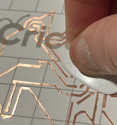
Smoothing down the copper traces with a guitar pick.

Take this Christmas tree for example, which uses a 555 timer and a CB4017 decade counter in order to drive some blinking LEDs. The ICs are through-hole, making the circuit fairly accessible to new players, but there are a few SMD components that need soldering as well. (More on that later.)

Here, the 555 acts like a clock and drives a square wave. Using the clock as input, the decade counter toggles the output pins one after the other, driving the LEDs to blink in turn. Since there are only eight lights, there is a pause in the light-up pattern, but that could be fixed by wiring decade counter output #9 to the reset pin.

Although function was the main focus circuit-wise, [Ben] managed to lay the traces in the shape of a Christmas tree, which looks great. Having done a similar project in the past, he discovered that the craft cutting machine prefers thick traces and wider spaces between them. This is largely why [Ben] chose to use through-hole ICs.

After laying everything out in KiCad, [Ben] exported the copper layer image for use on the cutting machine. Once it was all cut out, he put it on transfer tape to weed out the extra copper, and get the traces onto cardstock, the final substrate.

This is such a fun project, and we love that the CR2032 that powers it also acts as the stand in its vertical holder. Hit up GitHub if you want to make one for yourself. Want something even more 3D? Check out this hollow tree we saw a few years ago.

Breathtaking Alarm Clock Looks Like It Came From A 1960 Fallout Shelter

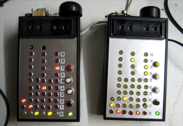
All the hardcore geeks have alarm clocks where the bell striker is a hard disk read head… or at least they’ll be building them after seeing this. [Senile Data Systems] created an industrial voltage alarm clock out of decade counters that looks like it was unearthed from a fallout shelter (machine translation).

At first glace you might mistake this for a binary clock since it uses a column of LEDs to indicate each digit of 24-hour time. It’s not, as each row corresponds to a pin on the CD4017 decade counters that make up the timekeeping circuit inside.

Thumbscrew wheel switches at the top of the bulky handheld unit are how the alarm time is set, triggering a bell along the top edge. The clock is driven by the 50 Hz line voltage and [SDS] tried using that AC to drive a solenoid as the striker on the prototype unit but it performed poorly. The use of a hard disk read head turns out to be the perfect striker, as heard in the video after the break. As for triggering from the decade counters, here’s what [SDS] told us about the design:

The switches’ outputs gets ANDed with a 10 Hz signal (on a 60 Hz grid it will become 12 Hz). This drives a slightly beefy transistor which in turn drives an electromagnet to hammer a bell which broke off my bicycle. Yes. This is a digital analog alarm clock. The clock portion is digital but the bell is analog and sounds like Grampa’s old wind up alarm clock.

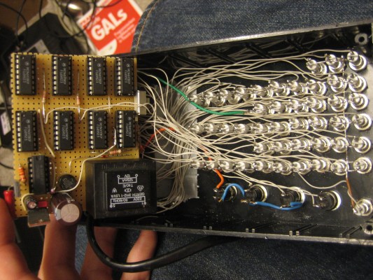
The build came about when a cache of over 600 industrial LEDs (24 V – 48 V) fell into his lap. This makes the insides of the clock something to behold as point-to-point soldering connects the panel mount lights and all nine logic chips. Add in that transformer for getting the line voltage and we imagine this thing has quite a bit of heft to it.

If you’ve ever had an alarm with a wind-up bell you know there’s no better way to jolt yourself out of a peaceful slumber and into the chaos of the real world. If the gentle tinkle of the hard drive head isn’t enough for you, this fire bell alarm clock will certainly do the trick.


Continue reading “Breathtaking Alarm Clock Looks Like It Came From A 1960 Fallout Shelter”

Random Numbers From Outer Space

Need a random number? Sure, you could just roll a die, but if you do, you might invite laughter from nearby quantum enthusiasts. If it’s truly, unpredictably random numbers you need, look no farther than the background radiation constantly bombarding us from the safety of its celestial hideout.

In a rare but much appreciated break from the Nixie tube norm of clock making, [Alpha-Phoenix] has designed a muon-powered random number generator around that warm, vintage glow. Muons are subatomic particles that are like electrons, but much heavier, and are created when pions enter the atmosphere and undergo radioactive decay. The Geiger-Müller tube, mainstay of Geiger counters the world over, detects these incoming muons and uses them to generate the number.

Inside the box, a 555 in astable mode drives a decade counter, which outputs the numbers 0-9 sequentially on the Nixie via beefy transistors. While the G-M tube waits for muons, the numbers just cycle through repeatedly, looking pretty. When a muon hits the tube, a second 555 tells the decade counter to stop immediately. Bingo, you have your random number! The only trouble we can see with this method is that if you need a number right away, you might have to go get a banana and wave it near the G-M tube.

Whether this all makes sense or not, you should check out [Alpha-Phoenix]’s project video, which is as entertaining as it is informative. He’s planning a follow-up video focused on the randomness of the G-M tube, so look out for that.

Looking for a cheaper way to catch your random numbers? You can do it with a fish tank, some air pumps, and a sprinkle of OpenCV.

Continue reading “Random Numbers From Outer Space”

Build Your Own LAN Cable Tester

Sure, you can buy a cable tester, but what fun is that? [Ashish] posted a nice looking cable tester that you can build with or without an onboard Arduino. If you don’t use an Arduino, the project uses a 555 chip to test the eight wires in an Ethernet cable. The readout is simple. When testing a conductor, one of 8 LEDs will light. If one doesn’t light, the cable is open. If more than one light up, there is a short. Mixed up pins will cause the LEDs to light out of sequence. You can see the device in the video below.

The 555 device is fine for the design and we were surprised that the project had provisions for using an Arduino as nothing more than a pulse generator. It could replace most of the circuit which is pretty simple. A decade counter converts the pulses into 8 pulses (a wiring change makes it reset on the 9th count). The rest of the circuit is nothing more than LEDs, resistors, and diodes.

Continue reading “Build Your Own LAN Cable Tester”

Always Misplacing Your Keys? You Can Fix That With Some Logic Chips

Every time he came home, it was the same thing. As soon as he crossed the threshold, his keys just disappeared. There was no other logical explanation for it. And whenever it was time to leave again, he had to turn the house upside down to find them.

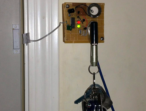
One day, [out-of-the-box] decided he’d had enough and built a door-activated alarm system out of stuff he had on hand—a decade counter, a cheapo reed switch-based door alarm, and some transistors. When the door is closed, the decade counter’s output is set to light up a green LED. When he comes home and opens the door, the reed switch closes, triggering the decade counter to shift its output to the next pin. The red LED comes on, and NPN transistor grounds the piezo, sounding the alarm. The only way to stop it is by inserting a shorted 1/4″ phone plug conveniently attached to his key ring into a jack on the circuit board until he hears that satisfying click of safe key-ping.

For those times when immediately plugging the keys into the wall isn’t feasible, or if his keys should disappear before he has the chance, there’s a momentary on the board that will stop the symphony of robotic cicadas blasting out from the piezo. It’s also good for family members who don’t want to play along or haven’t yet earned their 1/4″ plug.

Be sure to check out the build video after the break, which is just through that door there. And keep an eye on your keys, eh? Hackaday is not responsible for lost or stolen personal articles. Should you lose them, we can only suggest making a new car key from the spare and printing replacements for any standard keys.

Continue reading “Always Misplacing Your Keys? You Can Fix That With Some Logic Chips”

Using A Decade Counter To Make LEDs Flash

[Andrea De Napoli] created a LED display consisting of a half-dozen LEDs connected to the inverted signals of a CD4017 decade counter, giving the effect that a dark LED is running back and forth. The CD4017 works by activating 10 outputs, one at a time, as controlled by a clock signal sent to pin 14.

The first and last LEDs are lit by outputs 0 and 5 with the help of a PNP transistor and a 12K resistor. The middle four LEDs are switched by two outputs each and go dark when one of them goes high. [Andrea] really delves into the CD4017 and he shares a lot of detail in the project page.

Hackaday publishes a lot of posts about obscure ICs: Project 54/74 aims to create a database of die images of 5400 and 7400 series ICs. In a remix of a classic, the Baby 10 uses a 4017 to make a music sequencer. Continue reading “Using A Decade Counter To Make LEDs Flash”

The Design And Fabrication Of A Digital Clock

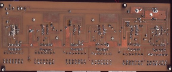
boarddesign

This clock is the first thing that [Kevin] ever made, way back before the Arduinofication of making, and long before the open hardware community exploded, and before the advent of cheap, custom PCBs. It’s an elegant design, with six seven-segment displays, a time base derived from line frequency, controlled entirely by 74-series logic chips. There was only one problem with it: it kinda sucked. Every so often, noise would become a factor and the time would be displayed as 97:30. The project was thrown in the back of the closet, a few revisions were completed, and 13 years later, [Kevin] wanted to fix his first clock.

The redesign used the same 1Hz timebase to control the circuitry, but now the timebase is controlled by a DS3231 RTC with an ATtiny85. The bridge rectifier was thrown out in favor of a much simpler 7805 regulator, and a new board was designed and sent off to OSHPark. Oh, how times have changed.

With the new circuitry, [Kevin] decided to construct a new case. The beautiful Hammond-esque enclosure was replaced with the latest and greatest of DIY case material – laser cut acrylic. Before, [Kevin] would put a jumper on the 1Hz timebase derived from the line frequency to set the clock – a task that makes plugging a clock in exactly at midnight a much simpler solution. Now, the clock has buttons to set the hours and minutes. Much improved, but still an amazing look at how far DIY electronics have come in a little over a decade.