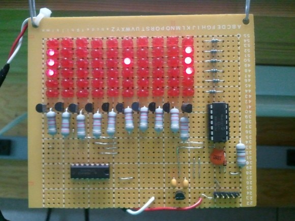
CMOS Logic Clock Tracks 24-hour Time

Here’s an IC logic project that displays 24-hour time. Planning was the name of the game for this project. [Mattosx] took the time to layout his design as a PCB in order to avoid the wiring nightmare when build with point-to-point connections.

Much of the complexity is caused by the display itself. Each of the six digits has its own binary-coded decimal chip and array of discrete resistors. Timekeeping is handled by six decade counters, two divider chips, one AND gate chip, and one OR gate chip. He chose a SOIC crystal oscillator chip as the clock signal. We’re more partial to the idea of using mains voltage as the clock signal.

[Mattosx] posted the board artwork if you’d like to etch your own 5″x8″ PCB. Just make sure you read through all of his notes as not all of the chips are oriented in the same direction.

[via Reddit]

Blinky Headgear

This hat has a chasing LED feature thanks to our old friend the 555 timer. [BananaSlug] even built in the option to change the speed at the push of a button.

His design starts out with a costume hat. Each of the 25 LEDs is soldered to a 2×4 hole chunk of protoboard. The LED package is pushed through a slit in the hat, but the protoboard remains on the inside where it can be sewn in place. From there [BananaSlug] soldered one negative bus around the circumference, and an individual positive lead from each module back to the control board. They’re addressed by a set of CD4017 decade counters which are clocked by the 555 timer circuit.

This is a great little analog/logic project and the style is perfect if you’ve got the coat to go along with it.

One Wire Reads The Keypad From The APRS Radio Mic

[Shane Burrell] decided to spend some time learning how the keypad on the his Kenwood TM-710A APRS radio mic works. It uses a different technique than you might think. Normally a grid of buttons is scanned as a matrix to detect keypresses, but this hardware actually counts pulses on a serial wire to take each reading.

The stock radio sends a steady digital pulse to the handset and with each pulse the mic pulls the line low. It then uses a 4017 decade counter to see what comes back. If the edge count matches it means nothing is pressed, but a change in the number of pulses returning to the base unit can be used to extrapolate which button has been pressed.

[Shane] went on to implement this control technique using an AVR chip in place of the  radio base unit. He used the data gained from measuring the pulse behavior using an oscilloscope to write the firmware for the project. He filmed a bit of a demo after the break which shows his findings.

We’re not quite sure how this would translate into your own home-brew projects, but the thought of scanning a keypad with two pins of a uC is quite desirable. Sure there is the 555-timer frequency technique, but we’re always down with new ideas.

Continue reading “One Wire Reads The Keypad From The APRS Radio Mic”

LED Matrix Shield Starts With A Very Loud Snap

We see a lot of LED matrix projects. They’re fun, and you can learn a lot of basic lessons during the build. But this one is out of the ordinary. [Rtty21] built an oddly sized, and sound controlled matrix shield for his Arduino. That’s it right there, the shield is the large chunk of protoboard but you can just see the Arduino peeking up over the top of it.

Now we say oddly sized because a 9×9 matrix doesn’t make much sense with an 8-bit micro controller. There’s no schematic but in the clip after the break he mentions that the columns and rows are driven by a decade counter and shift register and that’s what makes it possible to drive nine bits easily. Also of note on the board is that washer above and to the right of the matrix. It’s a touch-sensitive reset button. But the main control mechanism is a Clapper clone circuit. Just snap your fingers and it turns the project on or off. [Rtty21] based the design on this step-by-step sound input build.

Continue reading “LED Matrix Shield Starts With A Very Loud Snap”

Infrared Control For Appliances

[RB] at Embedded Lab sent in a great guide on how to control appliances with a remote control using a really clever implementation of a decade counter and IR receiver.

The build itself is very simple – just a relay connected to mains power and a handful of resistors and transistors. The device is controlled with a decade counter and an infrared module usually found tucked away in the bezel of a TV.

When everything is plugged in, the first pulse from the remote switches the relay on, providing power to the outlet. When a second pulse is received, the reset pin on the decade counter is activated, setting the device back to its original off state. It’s a pretty clever build, and could be built with parts lying around the bench.

The project is powered through wall power with the help of a transformer and a 7805 regulator, but we think the size could be reduced with a pass-through power enclosure – the circuit certainly is small enough. In all, a very nice, low component count build.

Nixie Frequency Counter Gone Timepiece

nixie clock hack

[Windell] of Evil Mad Scientist Laboratories took an ancient Nixie tube based frequency counter and converted it into a clock. The unit he got his hands on is an HP model that was still in great shape. He’s using an internally generated one second pulse as the clock signal, but some modifications are necessary to display time. That’s because the frequency counter is base 10 and clocks use a quirky combination of base 60 and base 12.

It wasn’t too much of a problem to rig up a system to track minutes and seconds. The tens digit for each is monitored by a couple of AND gates that he added to the mix. When they detect a ‘6’ the digit is reset and a pulse increments the next digit as the carry. This is more difficult to accomplish with the hours though. Minutes and seconds count from 0 to 59 but hours don’t start at 0. Instead of over-complicating the logic [Windell] used a bit of slight-of-hand. The Nixie tubes for the hours have been rewired so that when the counter is at 0, the filament in the shape of a 1 lights up. No difference in logic, just a translation that makes them display one digit higher than the actual count.

LED Matrix With A Gross Of Pixels

This LED matrix is arranged in a 24×6 pattern for message scrolling. There’s no etched boards here, making us wonder where [Syst3mX] found protoboard this long. He’s using an Arduino to drive the demonstration (clip after the break) but you can use any microcontroller with this setup. That’s because he’s using three shift registers for column data and a decade counter for row scanning, requiring just five control pins.

While you’re going to the trouble of ordering components, maybe you should try your hand at building a touch sensitive LED matrix too.

Continue reading “LED Matrix With A Gross Of Pixels”