Hackaday Prize Entry: A Mess Of VGA On A Breadboard

Before all our video games came over the Intertubes, before they were on CDs, and before they were on cartridges, video games were all discrete logic. Pong was the first and you can build that out of several dozen logic chips. The great [Woz] famously built Breakout out of 44 simple chips.

For [Marcel]’s entry to the Hackaday Prize, he’s taking the single board microprocessor-less computer to the next level. He’s building a multi-Megahertz 64-color computer on a breadboard. What’s the capacitance of a breadboard? Just ask [Marcel].

The design of this disintegrated computer has just about everything you could want in a discrete CPU. There is no microcontroller or complex chips like the 74181 ALU, there’s pipelining with sometimes two instructions per clock, decoding with diodes, and a 60 Hz, 64 color VGA output and four sound channels. There’s only about 40 TTL chips on this board.

The project logs for this Hackaday Prize entry are a treat in themsleves, ranging from topics to the implementation of NES controllers to getting rid of the breadboard and turning this computer into something like a vintage game system, but with a custom CPU and instruction set. It’s an amazing build, and an awesome project for the Hackaday Prize.

Continue reading “Hackaday Prize Entry: A Mess Of VGA On A Breadboard”

Relay Computer: You Can Hear It Think

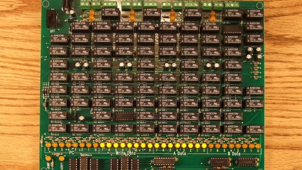
Modern digital computers have complex instruction sets that runs on state-of-the-art ALUs which in turn are a consequence of miniaturized logic gates that are built with tiny transistors. These tiny transistors are essentially switches. You could imagine replacing with electromagnetic relays, and get what is called a relay computer. If you can imagine it, someone’s done it. In this case, [jhallenworld].

The Z3 was the first working programmable, fully automatic digital computer designed by Konrad Zuse. The board employs modern semiconductor devices such as memory and microcontrollers, however, the CPU is all relays. A hexadecimal keyboard allows for program entry and a segment display allows tracking the address and data. The program is piped into serial to the parallel decoder and fed to the CPU where the magic happens. Since the core is electromechanical it is possible to connect the output to peripherals such as a bell as demonstrated near the end of the video.

This project is a good balance of retro and modern to be useful to anyone interested in mechanical computers and should be a lot of fun for the geek kind. Hacking this computer to modify the instruction set should be equally rewarding and a good exercise for students of computing theory.

There is a SourceForge page dedicated to the project with the details on the project including the instruction set and architecture. Check out the video below and if you are inspired by the project, be sure to check out the [Clickity Clack]’a Videos on designing a relay computer bit by bit.

Dis-Integrated 6502 Running Programs; Acting Like Computer

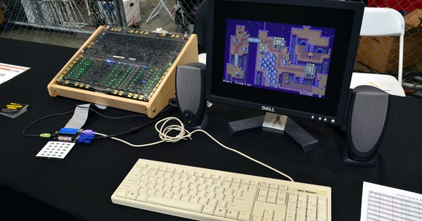
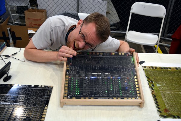
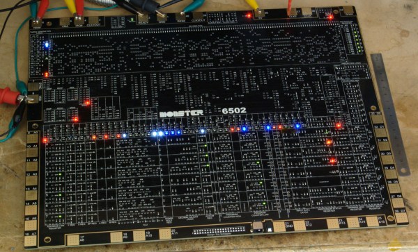
[Eric Schlaepfer] tends to turn up to Maker Faire with projects you simply don’t want to miss. This year is no different. Twelve months ago we delighted in seeing his 6502 processor built from an enormous reel of discrete MOSFETs. At the time it was freshly built and running random code to happily blink the LEDs reflecting activity in the registers. This year he’s given that blinking meaning and is running real programs on his Monster 6502 processor.

Continue reading “Dis-Integrated 6502 Running Programs; Acting Like Computer”

Relay Computer Starts With An Adder That Makes A Racket

Computers built using discrete logic chips? Seen it. Computers from individual transistors? Impressive, but it’s been done. A computer built out of electromechanical relays? Bring on the ozone!

The aptly named [Clickity Clack]’s new YouTube channel promises to be very interesting if he can actually pull off a working computer using nothing but relays. But even if he doesn’t get beyond the three videos in the playlist already, the channel is definitely worth checking out. We’ve never seen a simpler, clearer explanation of binary logic, and [Clickity Clack]’s relay version of the basic logic gates is a great introduction to the concepts.

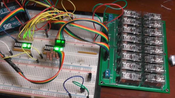
Using custom PCBs hosting banks of DPDT relays, he progresses from the basic AND and XOR gates to half adders and full adders, explaining how carry in and carry out works. Everything is modular, so four of his 4-bit adder cards eventually get together to form a 16-bit adder, which we assume will be used to build out a very noisy yet entertaining ALU. We’re looking forward to that and relay implementations of the flip-flops and other elements he’ll need for a full computer.

And pay no mind to our earlier dismissal of non-traditional computer projects. It’s worth checking out this discrete 7400 logic computer and this all-transistor build. They’re impressive too in their own way, if a bit quieter than [Clickety Clack]’s project.

Continue reading “Relay Computer Starts With An Adder That Makes A Racket”

How The Dis-integrated 6502 Came To Be

I made a bee line for one booth in particular at this year’s Bay Area Maker Faire; our friend [Eric Schlaepfer] had his MOnSter 6502 on display. If you missed it last week, the unveiling of a 6502 built from discrete transistors lit the Internet afire. At that point, the board was not fully operational but [Eric’s] perseverance paid off because it had no problem whatsoever blinking out verification code at his booth.

I interviewed [Eric] in the video below about the design process. It’s not surprising to hear that he was initially trying to prove that this couldn’t be done. Unable to do so, there was nothing left to do but devote almost six-months of his free time to completing the design, layout, and assembly.

What I’m most impressed about (besides just pulling it off in the first place) is the level of perfection [Eric] achieved in his design. He has virtually no errors whatsoever. In the video you’ll hear him discuss an issue with pull-up/pull-down components which did smoke some of the transistors. The solution is an in-line resistor on each of the replacement transistors. This was difficult to photograph but you can make out the soldering trick above where the 3-pin MOSFET is propped up with it’s pair of legs on the board, and the single leg in the air. The added resistor to fix the issue connects that airborne leg to its PCB pad. Other than this, there was no other routing to correct. Incredible.

The huge schematic binder includes a centerfold — literally. One of the most difficult pieces of the puzzle was working out the decode ROM. What folds out of this binder doesn’t even look like a schematic at first glance, but take a closer look (warning, 8 MB image). Every component in that grid was placed manually.

I had been expecting to see some tube-based goodness from [Eric] this year. That’s because I loved his work on Flappy Bird on a green CRT in 2014, and Battlezone on a tube with a hand-wound yoke last year. But I’m glad he stepped away from the tubes and created this marvelous specimen of engineering.

A Dis-Integrated 6502

The 6502 is the classic CPU. This chip is found in the original Apple, Apple II, PET, Commodore 64, BBC Micro, Atari 2600, and 800, the original Nintendo Entertainment System, Tamagotchis, and Bender Bending Rodriguez. This was the chip that started the microcomputer revolution, and holds a special place in the heart of every nerd and technophile. The 6502 is also possibly the most studied processor, with die shots of polysilicon and metal found in VLSI textbooks and numerous simulators available online.

The only thing we haven’t seen, until now, is a version of the 6502 built out of discrete transistors. That’s what [Eric Schlaepfer] has been working on over the past year. It’s huge – 12 inches by 15 inches – has over four thousand individual components, and so far, this thing works. It’s not completely tested, but the preliminary results look good.

The MOnSter 6502 began as a thought experiment between [Eric] and [Windell Oskay], the guy behind Evil Mad Scientist and creator of the discrete 555 and dis-integrated 741 kits. After realizing that a few thousand transistors could fit on a single panel, [Eric] grabbed the netlist of the 6502 from Visual6502.org. With the help of several scripts, and placing 4,304 components into a board design, the 6502 was made dis-integrated. If you’re building a CPU made out of discrete components, it only makes sense to add a bunch of LEDs, so [Eric] threw a few of these on the data and address lines.

This is the NMOS version of the 6502, not the later, improved CMOS version. As such, this version of the 6502 doesn’t have all the instructions some programs would expect. The NMOS version is slower, more prone to noise, and is not a static CPU.

So far, the CPU is not completely tested and [eric] doesn’t expect it to run faster than a few hundred kilohertz, anyway. That means this gigantic CPU can’t be dropped into an Apple II or commodore; these computers need a CPU to run at a specific speed. It will, however, work in a custom development board.

Will the gigantic 6502 ever be for sale? That’s undetermined, but given the interest this project will receive it’s a foregone conclusion.

Correction: [Eric] designed the 555 and 741 kits

Learning And Failing At Digital Electronics

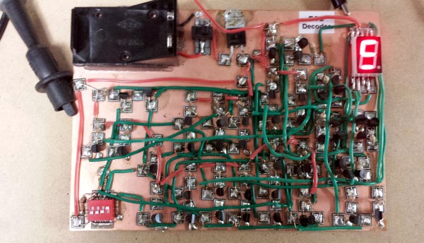
[spencerhamblin] is starting his explorations into digital electronics the hard way: reproducing a “simple” IC’s functionality by wiring up a board full of discrete transistors. In this case, the end product is a binary-to-seven-segment decoder built from scratch.

In engineering circles, this circuit is better known as a 7447 BCD to seven-segment decoder/driver, but just using a single chip has little pedagogical value. Building a simple circuit with 39 transistors, 31 resistors, and a handful of diodes is a good introduction to digital electronics, and after two attempts, [spencerhamblin] knocked it out of the park.

The build began with a piece of copper clad board, a bunch of cheap FETs from fleabay, and an incorrect schematic. While the first version of the project looked fantastic with Manhattan-style construction, and jumper wires everywhere, the schematic was fundamentally flawed and [spencer] got a little confused when converting the circuit to a common anode display.

Version two used a more standardized construction. This circuit was plotted in DipTrace, and the resulting PCB was sent off to OSHPark. The build was cleaner, but in capturing the schematic, [spencer] reversed the footprint of the seven segment display. That was easy enough to fix with a few short wires, and after a little bit of work [spencer] had a device that would convert binary to a seven segment display.