The apocalypse is coming, and the last time I checked, not many people have a semiconductor fab in their garage. We’ll need computers after the end of the world, and [matseng]’s project for the Hackaday Prize is just that – a framework to build computers out of discrete components.
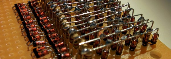
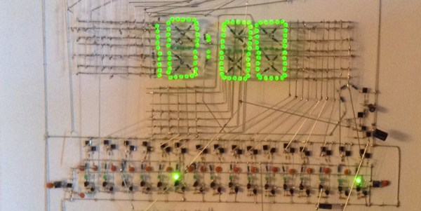
The apocalyptic spin on this project is slightly exaggerated, but there is a lot someone can learn by building digital devices out of transistors, resistors, and diodes. The building blocks of [matseng]’s computer are as simple as they come: he’s using three resistors, four diodes, and one NPN transistor to build a single NAND gate. These NAND gates can then be assembled into any form of digital logic. You’re never going to get a better visual example of functional completeness.
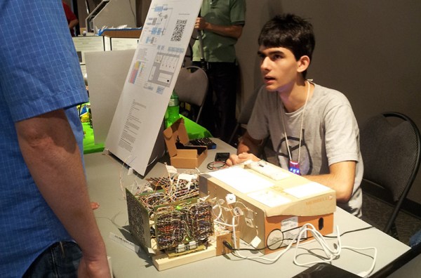
A project like this must be approached from both the top down and bottom up. To go from a high level to ones and zeros, [matseng] built an assembler and an emulator. Some ideas of what the instruction set will be are laid out in this project log, and for now [matseng] is going for a Harvard architecture with eight registers. It’s a lot of work for a computer that will be limited by how much memory [matseng] can be wired up, but as far as ambition goes, there aren’t many projects in the Hackaday Prize that can match this tiny, huge computer.

 By now we’ve all seen the ‘Three Fives’ kit from Evil Mad Scientist, a very large clone of the 555 timer built from individual transistors and resistors. You can do a lot more in the analog world with discrete parts, and


