Over the years as microcontrollers have become fast enough to do the heavy lifting, we have become used to 10 megabit Ethernet being bit-banged from interfaces it was never meant to emerge from. We think however that we’ve never seen one driven from an SPI interface, so this one from [Ivan] may be a first. With a cleverly designed transceiver using logic chips, it even offers a chance to understand something about the timing of an Ethernet interface, too.
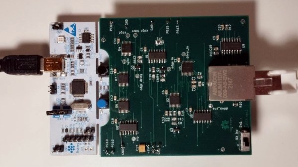
The differential logic signals derived from a simple Ethernet transceiver can be read by an SPI bus, but for the lack of a clock line. The challenge was then to construct a circuit the would construct the required clock pulses from the state changes on the data line. This would become a monostable with XOR gate, and a shift register to handle the clock during the preamble phase.
The resulting circuitry fits neatly on a shield for the ST Nucleo 64 board, where while it might not be the obvious choice for an Ethernet shield it certainly does the job.
Most readers will be familiar with Ethernet networks in some form, in particular the Cat5 cables which may snake around the back of our benches. In a similar vein, we’ll have used power over Ethernet, or PoE, to power devices such as webcams. Buy a PoE router or switch, plug in a cable, and away you go! But what lies behind PoE, and how does it work? [Alan] has written a comprehensive guide, based on experience working with the technology.
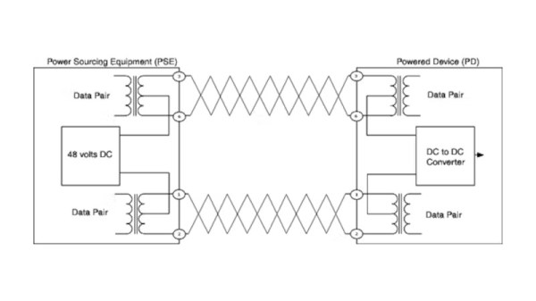
What we get first is a run-down of the various topographies involved. Then [Alan] dives into the way a PoE port polls for a PoE device to be connected, identifies it, and ramps up the voltage. Explaining the various different circuits is particularly valuable. The final part of the show deals with the design of a PoE module, with a small switching power supply to give the required 48 volts.
All in all, this should be required reading for anyone who works with Ethernet, because it’s one of those things too often presented as something of a black box. If you’re thirsty for more, it’s a subject Hackaday have touched on too in the past.
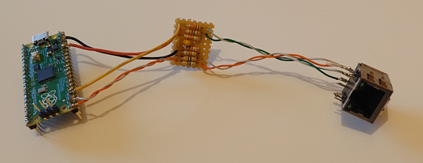
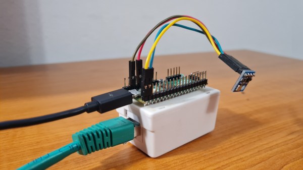
These days, even really cheap microcontroller boards have options that will give you Ethernet or WiFi access. But what if you have a Raspberry Pi Pico board and you really want to MacGyver yourself a network connection? You could do worse than check out this project by [holysnippet] that gives you a bit-banged bidirectional Ethernet port using only scrap passive components and software.
This project is similar to one we shared back in August by [kingyo], but differs in that what [holysnippet] has achieved is a fully-functional (albeit only around 7 Mbps) Ethernet port, rather than a simple UDP transmit device. The Ethernet connection itself is handled by the lwip stack. Connection to the RJ45 socket can be made from any of the Pi Pico pins, provided TX_NEG is followed directly by TX_POS, but the really hacky part is in the hardware.
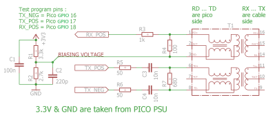
Schematic showing the empirically-determined passive component values required.
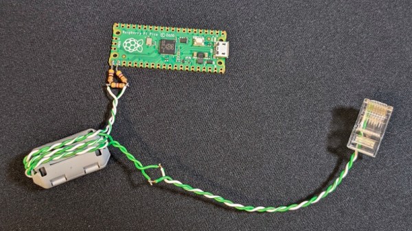
Rather than developing hardware that would protect the Pico, this design admits that it “shamefully relies on the Pico’s input protection devices” to limit the Ethernet voltages to 3.3 V.
You’ll need an isolation transformer from some old Ethernet-enabled gear (either standalone or as part of a magnetic jack), but then it’s only resistors and capacitors from there. There are warnings not to connect this to PoE networks for obvious reasons, and the component layout needs to keep in mind the ~20 MHz frequencies involved, but to get this working at all feels like quite a feat.
Normally, there’d be no reason to go to these lengths, but it’s always educational to see if it can be done and, with the current component shortages, this is another trick to keep up your sleeve for emergencies!
Putting ports where they shouldn’t belong is not a new idea, of course. Back in the day we even shared an inadvisable ATTINY implementation of bit-banged Ethernet with no protection at all.
A few days ago we covered a project that brought Ethernet connectivity to the Raspberry Pi Pico using little more than some twisted pair and a RJ-45 connector. It was a neat trick, but not exactly ready for widespread adoption. Looking to improve on things a bit, [tvlad1234] has taken that project’s code and rewritten it into a friendly library you can use with any RP2040 board.
In case you missed it, the initial demo did 10BASE-T transmission by bit-banging with the PIO, and was able to send UDP messages to devices on the wired LAN. It was an impressive accomplishment, but its code didn’t make it easy to build your project around it. This new library makes UDP messaging as easy as a printf, offloading all non-PIO-managed Ethernet signal work onto the RP2040’s second CPU core. The library even generates a random MAC address out of your flash chip’s serial number!
As a demonstration of the new library, [tvlad1234] has put together a simple Ethernet-connected temperature monitor using the BMP085 or BMP180 sensor connect over I2C. If you feel like you could use an Ethernet transmit-only sensor in your life, browsing the source code would be a great start.
Whilst the Raspberry Pi RP2040 is quite a capable little chip, on the whole it’s nothing really special compared to the big brand offerings. But, the PIO peripheral is a bit special, and its inclusion was clearly a masterstroke of foresight, because it has bestowed the platform all kinds of capabilities that would be really hard to do any other way, especially for the price.
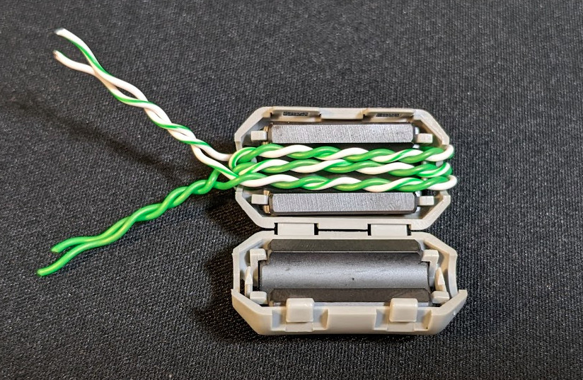
Our focus this time is on Ethernet, utilizing the PIO as a simple serialiser to push out a pre-formatted bitstream. [kingyo] so far has managed to implement the Pico-10BASE-T providing the bare minimum of UDP transmission (GitHub project) using only a handful of resistors as a proof of concept. For a safer implementation it is more usual to couple such a thing magnetically, and [kingyo] does show construction of a rudimentary pulse transformer, although off the shelf parts are obviously available for this. For the sake of completeness, it is also possible to capacitively couple Ethernet hardware (checkout this Micrel app note for starters) but it isn’t done all that much in practice.
Inside the expedient pulse transformer.
UDP is a simple Ethernet protocol for transferring application data. Being connection-less, payload data are simply formatted into a packet buffer up front. This is all fine, until you realize that the packets are pretty long and the bitrate can be quite high for a low-cost uC, which is why devices with dedicated Ethernet MAC functionality have a specific hardware serialiser-deserialiser (SERDES) block just for this function.
Like many small uC devices, the RP2040 does not have a MAC function built in, but it does have the PIO, and that can easily be programmed to perform the SERDES function in only a handful of lines of code, albeit only currently operating at 10 MBit/sec. This will cause some connectivity problems for modern switch hardware, as they will likely no longer support this low speed, but that’s easily solved by snagging some older switch hardware off eBay.
As for the UDP receive, that is promised for the future, but for getting data out of a remote device over a wired network, Pico-10BASE-T is a pretty good starting point. We’ve seen a few projects before that utilize the PIO to generate high speed signals, such as DVI, albeit with a heavy dose of overclocking needed. If you want a bit more of an intro to all things Pico, you could do worse than check out this video series we highlighted a while back.
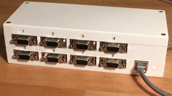
When it comes to impromptu enclosures, [Paul Wallace] is a man after our own hearts, for his serial-to-Ethernet converters allowing him to control older test equipment were housed in takeaway curry containers. Once the test equipment pile had grown it became obvious that a pile of curry containers was a bit unwieldy, even if the curry had been enjoyable, so he set about creating an all-in-one multiway serial to Ethernet box.
Reminiscent of the serial terminal access controllers that were found in dumb terminal sites back in the day, it’s a box with eight DB-9 connectors for serial ports and a single RJ45 Ethernet port. Inside is a Teensy 4.1 which packs a PHY and eight hardware serial ports, and a pile of MAX232 level converter modules. These have a small modification to wire in the CTS and RTS lines, and the whole is clothed in a custom 3D printed case.
The result is a very neat, almost commercial standard box that should save him quite a bit of space. Not everyone has eight devices to drive, so if you have just one how about using an ESP8266?
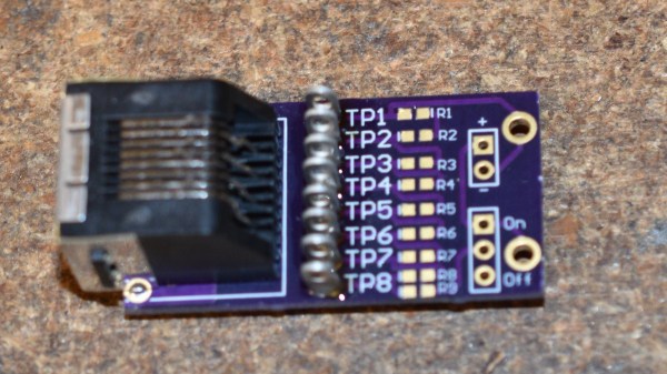
Ethernet cable testers are dime a dozen, but none of them are as elegant and multimeter-friendly as this tester from our Hackaday.io regular, [Bharbour]. An Ethernet cable has 8 wires, and the 9 volts of easily available batteries come awfully close to that – which is why the board has a voltage divider! On the ‘sender’ end, you just plug this board onto the connector, powered by a 9 volt battery. On the “receiver” end, you take your multimeter out and measure the testpoints – TP7 should be at seven volts, TP3 at three volts, and so on.
As a result, you can easily check any of the individual wires, as opposed to many testers which only test pair-by-pair. This also helps you detect crossover and miswired cables – while firmly keeping you in the realm of real-life pin numbers! This tester is well thought-out when it comes to being easily reproducible – the PCB files are available in the “Files” section, and since the “receiver” and “sender” PCBs are identical, you only need to do a single “three PCBs” order from OSHPark in order to build your own!