When you want to build a large format 3D printer, you can’t just scale up the design of a desktop machine. In an excellent four-part build series (videos after the break), [Dr. D-Flo] takes us through all the engineering challenges he had to contend with when building a 3D printer with a 4x4x4 ft (1.2 m cube) print volume.
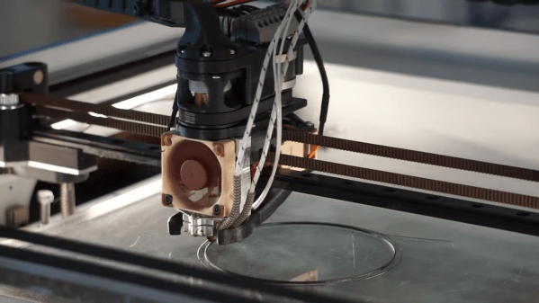
For such a large print volume you won’t be printing with a 0.4 mm nozzle. The heart of the printer is a commercial Massive Dimension MDPH2 pellet extruder, capable of extruding ~1 kg of plastic per hour through 1.5 mm to 5 mm nozzles. To feed the extruder, [Dr. D-Flo] used a Venturi vacuum system to periodically suck pellets from a large hopper. The system is driven by compressed air, which can introduce moisture back into the carefully dried pellets. To reduce the humidity levels, the compressed air passes through a series of vertical aluminum tubes to allow moisture to condense and drain out the bottom.
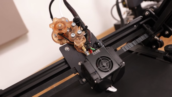
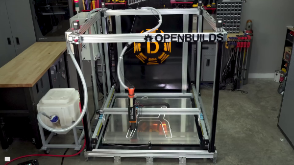
 At 8.4 kg, it needs a powerful motion platform to move it. [Dr. D-Flo] went with a stationary bed design, with the extruder pushed around by seven high torque NEMA23 motors on a large gantry built from C-beam aluminum extrusions. A machine this size needs to be very rigid with well-fitting parts, so [Dr. D-Flo] made heavy use of CNC machined aluminum parts.
To allow dynamic bed leveling, [Dr. D-Flow] made use of a Quad Gantry Leveling (GQL) scheme. This means that each of the four Z-actuators will dynamically adjust its position based on inputs from the leveling probe. The avoid stressing the corner mountings that hold the X-Y gantry to the Z carriage plates, he used radial spherical bearings at the mounting points to allow a few degrees of play.
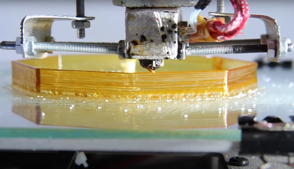
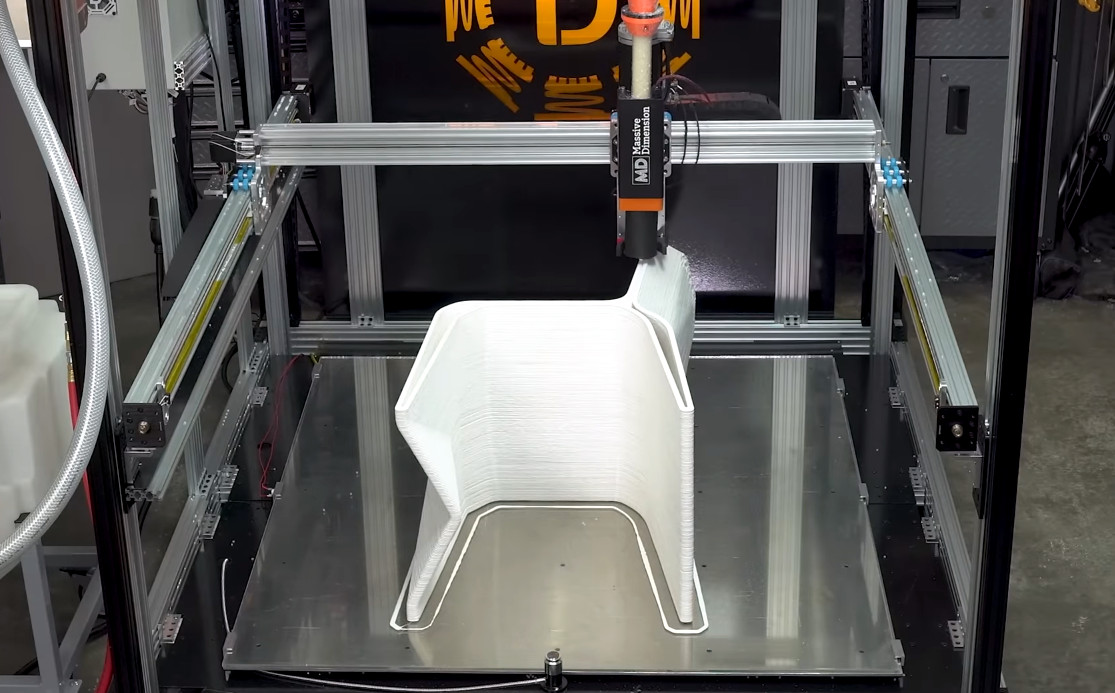
The build plate consists of an aluminum plate bolted onto the base in 25 positions with springs for adjustability. A massive 6000 watt 220 V heating pad sticks to the bottom, while the actual printing surface is a large sheet of borosilicate glass. One major concern was the deflection of the build plate when heated to working temperature, but with all the adjustment options [Dr. D-Flo] was able to get height variation down to about 0.25 mm. This is within the acceptable range when printing with layer heights of 1 mm or more.
We’ve featured large scale 3D printers in the past, but none are quite as big the University of Maine’s building-sized 3D printer that can print a motorboat in one piece.
Continue reading “Large Format 3D Printer Is A Serious Engineering Challenge”