The two largest manufacturers of FPGAs are, by far, Altera and Xilinx. They control over 80% of the market share, with Lattice and others picking up the tail end. The impact of this can be seen in EE labs and alibaba; nearly every FPGA dev board, every instructional, and every bit of coursework is based on Altera or Xilinx chips.
There’s a new contender from the east. Gowin Semiconductor has released two lines of FPGAs (Google translate) in just under two years. That’s incredibly fast for a company that appears to be gearing up to take on the Altera and Xilinx monolith.
The FPGA line released last week, the GW1N family, is comprised of two devices with 1,152 and 8,640 LUTs. These FPGAs are built on a 55nm process, and are meant to compete with the low end of Altera’s and Xilinx’ offerings. This adds to Gowin’s portfolio introduced last May with the GW2A (Google translate) family, featuring devices ranging from 18,000 to 55,000 LUTs and DSP blocks. Packages will range from easily solderable QFN32 and LQFP100, to BGA packages with more pins than an eighteenth century seamstress at the royal ball.
For comparison, Xilinx’ Spartan-6 LX family begins with devices featuring 3,840 LUTs and 216kb of block RAM, with larger devices featuring 147,443 LUTs and up to 268kb of block RAM. Altera’s Cyclone IV E devices are similarly equipped, with devices ranging from 6,272 to 114,480 LUTs. Between the two device families introduced by Gowin recently, nearly the entire market of low-end FPGAs is covered, and they’re improving on the current offerings: the GW1N chips feature random access on-chip Flash memory. Neither the low-end devices from Altera nor devices from Lattice provide random-access Flash.
The toolchain for Gowin’s new FPGAs is based nearly entirely on Synopsys’ Synplify Pro, with dedicated tools from Gowin for transforming HDL into a bitstream for the chip. This deal was inked last year. As for when these devices will make it to market, Gowin is hoping to send out kits to well-qualified devs soon, and the devices may soon show up in the warehouses of distributors.
Gowin’s FPGAs, in contrast to the vast, vast majority of FPGAs, are designed and fabbed in China. This gives Gowin a unique home-field advantage in the land where everything is made. With LVDS, DSP, and other peripherals these FPGAs can handle, Gowin’s offerings open up a wide variety of options to developers and product engineers a few miles away from the Gowin plant.
The GW1N and GW2A families of FPGAs are fairly small when it comes to the world of FPGAs. This limitation is by capability though, and not number of units shipped. It’s nearly tautological that the largest market for FPGAs would be consumer goods, and Gowin is focusing on what will sell well before digging in to higher end designs. We will be seeing these chips show up in devices shortly, and with that comes a new platform to tinker around with.
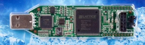
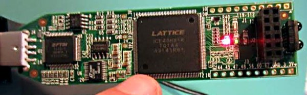
If you’re looking to make your mark on the world of open source hardware and software, you could do worse than to start digging into the synthesis and bitstream of these Gowin chips. Just months ago, Lattice’s iCE40 bitstream was reverse engineered, and already there are a few boards capitalizing on a fully open source toolchain for programmable logic. With more capable FPGAs coming out of China that could be stuffed into every imaginable product, it’s a golden opportunity for hardware hackers and developers alike.
[Thanks for the tip Antti]