If you’ve been thinking about playing around with FPGAs and/or are interested in CPU design, [Domipheus] has started a blog post series that you should check out. Normally we’d wait until the whole series is done to post about it, but it’s looking so good, that we thought we’d share it with you while it’s still in progress. So far, there are five parts.
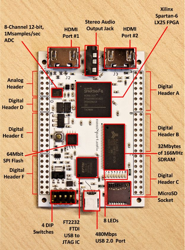 In Part One, [Domipheus] goes through his rationale and plans for the CPU. If you’re at all interested in following along, this post is a must-read. The summary, though, is that he’s aiming to make a stripped-down 16-bit processor on a Spartan 6+ FPGA with basic arithmetic and control flow, and write an assembler for it.
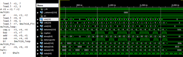
In Part Two, [Domipheus] goes over the nitty-gritty of getting VHDL code rendered and uploaded to the FPGA, and as an example builds up the CPU’s eight registers. If you’re new to FPGAs, pay special attention to the test bench code at the end of the post. Xilinx’s ISE package makes building a test suite for your FPGA code pretty easy, and given the eventual complexity of the system, it’s a great idea to have tests set up for each stage. Testing will be a recurring theme throughout the rest of the posts.
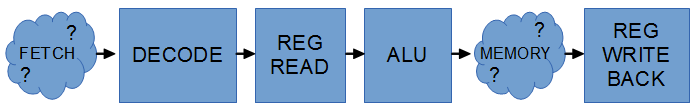
In Part Three, [Domipheus] works through his choices for the instruction set and starts writes up the instruction set decoder. In Part Four, we get to see an ALU and the jump commands are implemented. Part Five builds up a bare-bones control unit and connects the decoder, ALU, and registers together to do some math and count up.
We can’t wait for further installments. If you’re interested in this sort of thing, and are following [Domipheus]’s progress, be sure to let him know: we gotta keep him working.
Of course, this isn’t the first time anyone’s built a soft-CPU in an FPGA. (The OMG was added mostly to go along with the other TLAs.) Here’s a tiny one, a big one, and a bizarre one.