 Flappy Bird has been ported to just about every system imaginable, including but not limited to the Apple II, Commodores, pretty much every version of the Atari, and serves as a really great demonstration of the TI-99’s graphics capabilities. Porting is one thing, but having a computer automate Flappy Bird is another thing entirely. [Ankur], [Sai], and [Ackerly] in [Dr. Bruce Land]’s advanced microcontroller design class at Cornell have done just that. They’re playing Flappy Bird with a camera, FPGA, and a penny wired up to a GPIO pin to guide the little 8-bit-bird through Mario pipes.
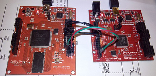
The setup the team is using consists of a webcam that records the screen of a smartphone, an FPGA, and a little bit of circuitry to emulate screen taps. Inside the FPGA, the team is looking at the video stream from the phone to detect the bird, pipes, and gaps. The ‘tapper’ unit is a US penny, placed right above the ‘tap’ button, wired to a GPIO port. This was found to be the ideal contact for a capacitive touch screen – taps that were too small weren’t registered, and taps that were too big registered as two taps.
For spending an entire semester on automating Flappy Bird, the team has a lot of knowledge to show for it, but not the high score: the bird only makes it through the first pipe 10% of the time, and the second pipe 1% of the time. The high score is three. That’s alright – getting the algorithm right to play the game correctly was very, very difficult, and to nail that problem down, they estimate it would take at least another semester.