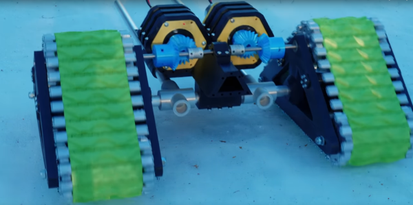
While wheels might seem like a foundational technology, they do have one major flaw: they typically need maintained roads in order to work. Anyone who has experience driving a Jeep or truck off-road likely knows this first-hand. For those with extreme off-road needs the track is often employed. [Let’s Print] is working on perfecting his RC tracked vehicle to take advantage of these perks using little more than 3D printed parts and aluminum stock.
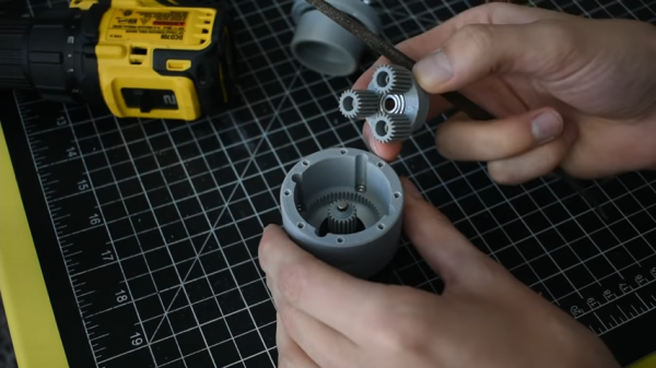
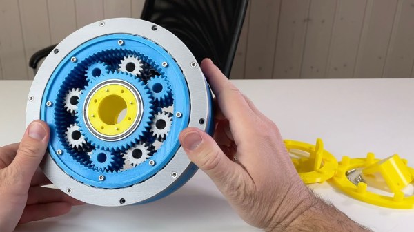
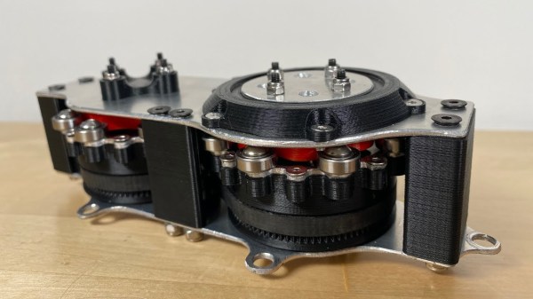
This vehicle doesn’t just include the 3D printed tracks, but an entire 3D printed gearbox and drivetrain to drive them. Each track is driven by its own DC motor coupled to a planetary gearbox to give each plenty of torque to operate in snow or mud. The gearbox is mated to a differential which currently shares a shaft, which means that steering is currently not possible. The original plan was to have each motor drive the tracks independently but a small mistake in the build meant that the shaft needed to be tied together. [Let’s Print] has several options to eventually include steering, including an articulating body or redesigning the drivetrain to be able to separate the shaft.
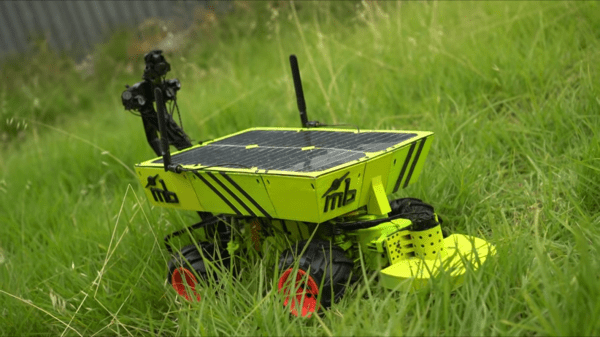
While this vehicle currently has no wheels in order to improve traction, [Let’s Print] does point out that a pair of wheels could complement this vehicle when he finished the back half of it since wheels have a major advantage over tracks when it comes to steering. A vehicle with both could have the advantages of both, so we’re interested to see where this build eventually goes.
Thanks to [Joonas] for the tip!
Continue reading “Tracked RC Vehicle Is (Mostly) 3D Printed”