The greatest threat to a potted plant stems from its owner’s forgetfulness, but [Sasa Karanovic] has created an automation system that will keep his plants from getting too thirsty. Over the past year [Sasa] has been documenting an elegant system for monitoring and watering plants which has now blossomed into a fully automated solution.
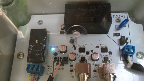
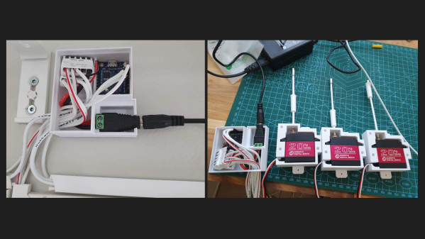
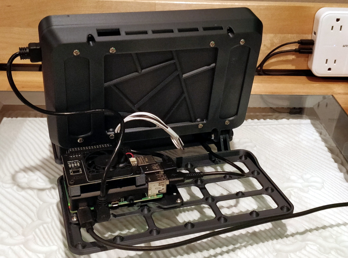
If you haven’t seen the earlier stages of the project, they’re definitely worth checking out. The short version is that [Sasa] has developed a watering system that uses I2C to communicate with soil moisture, temperature, and light sensors as well as to control solenoids that allow for individual plants to be watered as needed. An ESP32 serves as a bridge, allowing for the sensors to be read and the water to be dispensed via an HTTP interface.
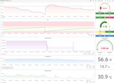
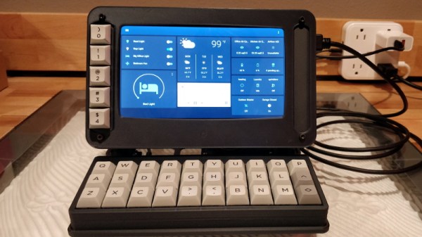
In this final part, [Sasa] integrates his watering system into a home automation system. He uses a MySQL database to store logs of sensor data and watering activity, and n8n to automate measurement and watering. If something isn’t quite right, the system will even send him a Telegram notification that something is amiss.
If you think automation might be the best way to save your plants from a slow death, [Sasa] has kindly shared his excellent work on GitHub. Even if you don’t have a green thumb, this is still a great example of how to develop a home automation solution from scratch. If you’re more interested in television than gardening, check out [Sasa]’s approach to replacing a remote control with a web interface!
Continue reading “Automation Allows You To Leaf Your Plants Alone”