If you want smart light switches in your house, you can buy from any one of hundreds of manufacturers. [Brian Boyle] had kitted out his home with TP Link devices, but after a few years of use, he found they all suddenly failed within a few months of each other. Decrying the state of things, he set about building his own instead.
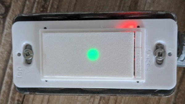
[Brian]’s switches use the ESP32 for its handy in-built WiFi hardware. His aim was to produce smart switches that would fit neatly into standard “Decor” style switch boxes. The design uses two PCBs. One is charged with handling the mains power side of things. It carries an SPDT relay for switching AC power, and a DC power supply to run the ESP32 itself. The controller board holds the microcontroller, a Neopixel as a status indicator, and a pair of buttons — one for switching the lights on and off, the other for resetting to default settings. The physical housing is 3D printed, and looks great with the glowing status indicator in the middle of the switch.
[Brian]’s switches are triggerable via MQTT, a web interface, and the physical button onboard the device itself. Having built the devices on his own, he’ll be well-placed to troubleshoot any usability or reliability issues that crop up in the future. That’s a lot more than we can say about most smart devices on the market!