Power Log Splitting: Trying (and Sometimes Failing) To Build A Better Ax

Wood. Humans have burned it for to heat their homes for thousands of years. It’s truly a renewable source of energy. While it may not be the most efficient or green method to warm a space, it definitely gets the job done. Many homes still have a fireplace or wood burning stove for supplemental heat. For those in colder climates, wood is more than just supplemental, it’s needed simply for survival.

Splitting maul by Chmee2 via Wikipedia

The problem with firewood is that it doesn’t come ready to burn. Perfect fireplace sized chunks don’t grow on trees after all. The trees have to be cut up into logs. The logs must be split. The split wood then needs to dry for 6 months or so.

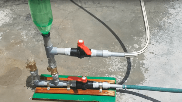
Anyone who’s spent time manually splitting wood can tell you it’s back breaking work. Swinging an 8 pound maul for a few hours will leave your hands numb and your shoulders aching. It’s the kind of work that leaves the mind free to wander a bit. The hacker’s mind will always wander toward a better way to get the job done. Curiously we haven’t seen too many log splitting hacks here on the blog. [KH4] built an incredible cross bladed axe back in 2015, but that’s about it.

Continue reading “Power Log Splitting: Trying (and Sometimes Failing) To Build A Better Ax”

Retrotechtacular: Häfla Hammerforge Healed

Visit any renaissance fair across the United States this fall and you’ll undoubtedly find a blacksmith. He’ll be sweating away in a tent, pounding on a piece of glowing steel set against an anvil. While the practice of the single blacksmith endures today, high-production ‘works of days past required increasing amounts of muscle. The more tireless the muscle, the better. The manual efforts of the blacksmith were replaced by huge hammers, and the blacksmith needed only to turn the piece between impressions and maintain a healthy respect for the awesome crushing power of the machine.

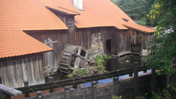
Last week, blacksmith enthusiasts completed restoration work on the Häfla hammer in Finspang, Sweden. The 333 year old hydraulic hammer hadn’t been used since 1924, when operations ceased at the Häfla Hammerforge. The ‘works was built in 1682 and used the German method of forging, which had been introduced to Sweden in the 1500s. Steel production was revolutionized in the 1800s by the Bessemer process, which resulted in a much stronger product. Continue reading “Retrotechtacular: Häfla Hammerforge Healed”

Retrotechtacular: Principles Of Hydraulic Steering

Have you ever had the pleasure of trying to steer a one-ton pickup from the 1940s or wondered how hard it would be to turn your car without power-assisted steering? As military vehicles grew larger and heavier in WWII, the need arose for some kind of assistance in steering them. This 1955 US Army training film handily explains the principles of operation used in a hydraulically-assisted cam and lever steering system.

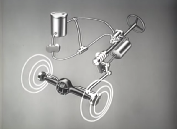
The basic steering assembly is described first. The driver turns the steering wheel which is attached to the steering shaft. This shaft terminates in the steering cam, which travels up or down along the camshaft depending on the direction steered. The camshaft connects to the steering shaft through a spline joint, which keeps the travel from extending to the steering wheel. The steering cam is connected to the Pitman arm lever and Pitman arm shaft. Movement is transferred to the Pitman arm, which connects to the steering linkage with a drag link.

The hydraulic system helps the Pitman arm drive the linkage that turns the wheels and changes the vehicle’s direction. The five components that comprise the hydraulic system use the power of differential pressure, which takes place inside the power cylinder. The hydraulic system begins and ends with a reservoir which houses the fluid. A pump driven by the engine sends pressurized fluid through a relief valve to the control valve, which is the heart of this system.

Continue reading “Retrotechtacular: Principles Of Hydraulic Steering”

Ask Hackaday: Who Is Going To Build This Pneumatic Transmission Thing?

fluid_transmission

Disney research is doing what they do best, building really cool stuff for Disney and telling the rest of the world how cool they are. This time, it’s a very low friction fluid transmission device designed for animatronics.

From testing a few toy robotic arms, we can say without a doubt that servos and motors are not the way to go if you’re designing robots and animatronics that need lifelike motion. To fix this, a few researchers at Disney Pittsburgh have turned to pneumatics and hydraulics, where one joint is controlled by two sets of pistons. It’s extremely similar to the pneumatic LEGO, but more precise and much more lifelike.

The system uses a pair of cylinders on each joint of a robot. Disney is using a rolling diaphragm to seal the working fluid in its tubes and cylinders. This is an extremely low-friction device without any shakiness or jitters found with simple o-ring pneumatics and hydraulics.

The system is backdriveable, meaning one robotic arm can control another, and the other way around. Since we’re dealing with hydraulics, the cylinders (and robotic/animatronic devices) don’t need to be the same size; a small device could easily control a larger copy of itself, and vice versa.

The devices are fairly simple, with gears, toothed belts, and bits of plastic between them. The only unique part of these robots is the rolling diaphragm, and we have no idea where to source this. It looks like it would be great for some robotics or an Iron Man-esque mech suit, but being able to source the components will be a challenge.

You can check out the videos of these devices below, and if you have any idea on how to build your own, leave a note in the comments.

Continue reading “Ask Hackaday: Who Is Going To Build This Pneumatic Transmission Thing?”

Snake-bot Gives Us The Mechanical Heevy-jeevies

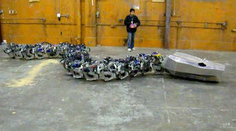
Basilisk? Nope, just your run-of-the-mill giant serpentine robot build. This build aims to recreate Titanoboa, a prehistoric snake which measured more than fifty feet long and weighted over a ton. They’re well on their way to completing the goal, as what you see above is fully operational, lacking only cosmetic niceties which would only serve to make the beast less horrifying.

The video after the shows the snake getting round an open space, presumably at the eatArt headquarters in Vancouver. You may remember the team from one of their other builds also featured in that clip, the Mondo Spider. Eventually, the snake will have a rider just like the spider does, sitting in a saddle mounted just behind the head. There’s few details about the hardware, but we know it’s hydraulic, and that they raised $10k to make the build possible.

For some reason seeing these bots interact gives us flashbacks to childhood cartoons. Is it possible the eatArt crew has been watching too many old G.I. Joe cartoons and the like?

Continue reading “Snake-bot Gives Us The Mechanical Heevy-jeevies”

Parallel Parking System

parking

Autoblog dug up this classic mechanical engineering project from 2006. A team of five University of Toledo students constructed a system to help parallel park a car. First, you drive nose first into the space. Hydraulic rams then lower the drive wheel out of the trunk, raising the rear of the car. The single wheel is also hydraulically driven and moves the car into the space. They have a blog documenting the six week build. Have a look at the demonstration video below.

Continue reading “Parallel Parking System”