PJON, pronounced like the iridescent sky rats found in every city, is a cool one wire protocol designed by [gioblu].
[gioblu] wasn’t impressed with the complications of I2C. He thought one-wire was too proprietary, too complicated, and its Arduino implementations did not impress. What he really wanted was a protocol that could deal with a ton of noise and a weak signal in his home automation project with the smallest amount of wiring possible.
That’s where is his, “Padded Jittering Operative Network,” comes in. It can support up to 255 Arduinos on one bus and its error handling is apparently good enough that you can hold an Arudino in one hand and see the signals transmitted through your body on the other. The fact that a ground and a signal wire is all you need to run a bus supporting 255 devices and they’ll play nice is pretty cool, even if the bandwidth isn’t the most extreme.
Aside from the cool of DIY protocols. We really enjoyed reading the wiki describing it. Some of the proposed uses was running your home automation through your ducting or water pipes (which should be possible if you’re really good at isolating your grounds). Either way, the protocol is neat and looks fun to use. Or check out PJON_ASK if you want to do away with that pesky single wire.
[Alvaro Ferrán Cifuentes] has built the coolest motion capture suit that we’ve seen outside of Hollywood. It’s based on tying a bunch of inertial measurement units (IMUs) to his body, sending the data to a computer, and doing some reasonably serious math. It’s nothing short of amazing, and entirely doable on a DIY budget. Check out the video below the break, and be amazed.
Cellphones all use IMUs to provide such useful functions as tap detection and screen rotation information. This means that they’ve become cheap. The ability to measure nine degrees of freedom on a tiny chip, for chicken scratch, pretty much made this development inevitable, as we suggested back in 2013 after seeing a one-armed proof-of-concept.
But [Alvaro] has gone above and beyond. Everything is open source and documented on his GitHun. An Arduino reads the sensor boards (over multiplexed I2C lines) that are strapped to his limbs, and send the data over Bluetooth to his computer. There, a Python script takes over and passes the data off to Blender which renders a 3D model to match, in real time.
All of this means that you could replicate this incredible project at home right now, on the cheap. We have no idea where this is heading, but it’s going to be cool.
Historically when hams built low power (QRP) transmitters, they’d use a crystal to set the frequency. Years ago, it was common to find crystals in all sorts of radios, including scanners and handheld transceivers. Crystals are very stable and precise and it is relatively easy to make a high quality oscillator with a crystal and a few parts.
The big problem is you can’t change the frequency much without changing crystals. Making a high quality variable frequency oscillator (VFO) out of traditional components is quite a challenge. However, today you have many alternatives ranging from digital synthesis to all-in-one IC solutions that can generate stable signals in a wide range of frequencies.
[N2HTT] likes to build radio projects and he decided to take an Si5351 clock generator and turn it into a three frequency VFO for his projects. The Si5351 uses a crystal, so it is very stable. However, you can digitally convert that crystal frequency into multiple frequencies over a range of about 8kHz to 160MHz.
Sometimes the most mundane products have surprisingly sophisticated internals. What’s in a game controller? If it is a Wii remote, you’ll find a lot inside–an IR sensor, Bluetooth, an accelerometer, and EEPROM. It also has a six pin expansion port that allows I2C peripherals connect to the controller.
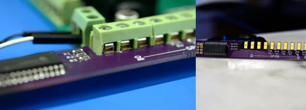
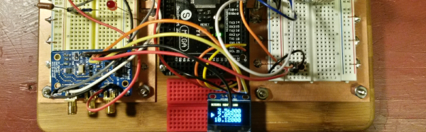
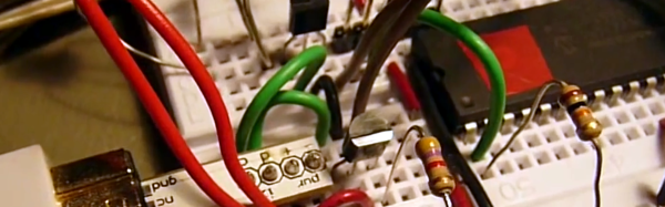
[DotMusclera] wanted to experiment with a gyroscope and decided to hook up to the Wii MotionPlus to a Microchip PIC. Using information from the WiiBrew wiki, [DotMusclera] connected a PIC18F4550, an LCD, and a handful of components (mostly to do 3.3V level conversion), he set up the hardware on a breadboard. The only odd part you might have to work around is a Wii breakout board that converts from the breadboard to the Wii interface.
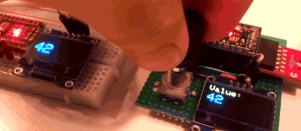
The software is easy to follow since it is written in Hi-TECH C and well-commented. The hardware lacks a schematic, but from the parts list and the video, you can probably figure it out. The setup works well and shows roll, pitch, and yaw on the LCD screen.
The project log is very detailed, with a lot of information about gyroscopes and the communication format the gyro uses. The video demo is worth watching as well.
The Microsoft Surface is an awesome Tablet PC, but it has one problem: there is just one USB port on it. There is an additional port, though: a connector for the Surface Touch Keyboard connector. That’s what [Edward Shin] is looking into, with the long-term intention of creating an adapter that allows him to connect a Thinkpad keyboard to this proprietary connector. His initial work identified the connector as using Microsoft’s own HID over I2C protocol, which sends the standard USB HID protocol over an I2C connection. So far so good, but it seems to get a little odd after that, with a serial connection running at nearly 1 Mbps and sending 9 bits per transfer with 1 stop bit. Presumably this is because Microsoft had planned to release other devices that used this connector, but this hasn’t panned out so far.
Anybody want to help him out? He has posted some captured data from the connection for analysis, and is looking for assistance. We hope he manages to build his converter: a Microsoft Surface with a decent keyboard and an open USB port would be a great portable setup. Bonus: for those teardown fans among you, he has done a great teardown of a Touch Cover keyboard that reveals some interesting stuff, including a lot of well-labelled test points.
Last week, I covered some of the bitter details of an interesting hack that lets us split up the I²C clock line into multiple outputs with a demultiplexer, effectively giving us “Chip Selects” for devices with the same address.
This week, I figured it’d be best to layout a slightly more practical method for solving the same problem of talking to I²C devices that each have the same address.
I actually had a great collection of comments mention the same family of chips I’m using to tackle this issue, and I’m glad that we’re jumping off the same lead as we explore the design space.
Recalling the Work of Our Predecessors
Before figuring out a clever way of hacking together our own solution, it’s best to see if someone before us has already gone through all of the trouble to solve that problem. In this case–we’re in luck–so much that the exact bus-splitting behavior we want is embedded into a discrete IC, known as the PCA9547.
It’s worth remembering that our predecessors have labored tirelessly to create such a commodity piece of silicon.
The PCA9547 (PDF) is an octal, I²C bus multiplexer, and I daresay, it’s probably the most practical solution for this scenario. Not only does the chip provide 8 separate buses, up to seven more additional PCA9547s can be connected to enable communication with up to 64 identical devices! What’s more, the PCA9547 comes with the additional benefit of being compatible with both 3.3V and 5V logic-level devices on separate buses. Finally, as opposed to last week’s “hack,” each bus is bidirectional, which means the PCA9547 is fully compliant with the I²C spec.
Selecting one of the eight I²C buses is done via a transfer on the I²C bus itself. It’s worth mentioning that this method does introduce a small amount of latency compared to the previous clock-splitter solution from last week. Nevertheless, if you’re planning to read multiple devices sequentially from a single bus anyway, then getting as close-as-possible to a simultaneous read/write from each device isn’t likely a constraint on your system.
With a breakout board to expose the pads, I mocked up a quick-n-dirty Arduino Library to get the conversation started and duplicated last week’s demo.
Happily enough, with a single function to change the bus address, the PCA9547 is pretty much a drop-in solution that “just works.” It’s definitely reassuring that we can stand on the shoulders of our chip designers to get the job done quickly. (They’ve also likely done quite a bit more testing to ensure their device performs as promised.) Just like last week, feel free to check out the demo source code up on Github.
There comes a time when you need to wire up three, four, or more identical i2c devices to a common microcontroller. Maybe you’re thinking about driving 128 seven-segment displays with eight of those MAX6955 16-way digit drivers, or maybe you have a robot full of joints–each of which needs a BNO055 inertial sensor for angle estimation. (See above.) Crikey! In both of those cases, you’re best bet might be a schnazzy I²C device that can do most of the work for you. The problem? With a single I²C bus, there’s no standard way defined in the protocol for connecting two or more devices with the same address. Shoot! It would’ve been handy to wire up three BNO055 IMUs or eight MAX6955s and call it a day. Luckily, there’s a workaround.
We’ve seen some clever tricks in the past for solving this problem. [Marv G‘s] method involves toggling between a device’s default and alternate address with an external pin. This method, while clever, assumes that the device (a) has an alternate I²C address and (b) features an external pin for toggling that address.
I’ll introduce two additional methods for getting the conversation started between your micro’ and your suite of identical sensors. The first is “a neat trick,” but somewhat impractical for widespread use. The second is far more production-worthy–something you could gloat over and show off to your boss! Without further ado, let’s get started with Method 1.
Lastly, if you’d like to follow along, feel free to check out the source code on Github.
In both methods, I’m using the same sensor setup to check that each circuit behaves correctly. I happened to have a bunch of extra BMA180s on the bench, so I rolled out an example based on these chips. Back in the day, the BMA180 was a pretty common three-axis digital accelerometer. It has an I²C interface with two optional addresses. For the purpose of this example, I’m fixing them all with the same address. I’ve mounted three of these guys on mutually perpendicular axes of my acrylic “test cube,” and I’m reading each chip’s Z-axis. In this configuration I can easily pick out the gravity vector from the corresponding sensor as the data goes flying by my serial port window. If I can uniquely address each sensor and read the data, I’ve got a working circuit.
Method 1: Splicing Clocks into Chip-Selects
This method tips its hat towards SPI in that it behaves in an oddly similar fashion. If you’re feeling rusty on SPI, here’s a quick recap.
A Quick SPI Refreshment:
SPI, like I²C, is another protocol that shares both its clock and data lines with multiple slave devices. The difference, though, lies in the addressing scheme to talk to these devices that share the same bus. With SPI, while clock and data lines are shared, devices are addressed with separate chip-select (CS) lines.
The master microcontroller dedicates a unique output pin to each device (~SS1, ~SS2, and ~SS3 in this illustration). When the master micro’ wants to talk to a device, it asserts that device’s chip-select input pin by pulling it to logic LOW, and the conversation begins over the data bus. With the chip select LOW, the corresponding slave listens to the data on the bus. Meanwhile, all other devices ignore the conversation between the master and it’s chosen slave by keeping their bus pins in a high impedance state.
Giving I²C Its Own Chip-Selects:
With I²C, Clock (SCL) and Data (SDA) lines are still shared between all I2C slave devices, but the addressing scheme happens by sending a message heard by all devices on the bus. To single out one device on the shared bus, the master first passes down the address of the slave device it wants to talk to, after which that slave replies with an ACKnowledge, and all other slaves ignore the data that follows until both data transmission is complete and the bus is “released.”
Because we have the problem of multiple devices with shared addresses, in theory, all of these devices would reply when the master passes down their shared address, and there’s no way for the master to single out a single device. In reality, this behavior is undefined on the I²C protocol.
Yikes! Anything goes when we wander away from defined behavior, so we try to avoid these things in practice.
The solution?
According to the I²C spec, It just so happens that an I²C slave device will ignore changes on the data line (SDA) provided that the clock line (SCL) is held high. In this method, I’ll “split” the SCL line into multiple SCL lines such that each shared I²C device gets its own SCL. By selectively rerouting the clock to each I²C device one-at-a-time, I’ve essentially turned the SCL line into a “chip select.”
To chop up that clock line, I’ll need a demultiplexer. A demultiplexer (or decoder) takes a logical input and reroutes it to one of several outputs based on the binary select lines.
I’ve dropped in the 74AC11138 eight-way demultiplexer for this task. It’s fast, capable of switching at megahertz rates, and its outputs default to logic HIGH. That second note is handy since idle SCL lines also default to logic HIGH.
The setup is shown in a simplified schematic above. In it, I’m using a Teensy 3.0 posing as the I²C bus master. To the right of the Teensy is the collection of identical chips, BMA180 accelerometers in this case. In the middle is the 74AC11138 eight-way demultiplexer.
Cons of this Method:
There’s a minor drawback with this technique, though, in that it doesn’t support I²C’s clock-stretching feature. Taking a step back, this method assumes that the SCL line is inherently unidirectional, controlled by only the I²C bus master. In other words, we’re making the assumption that data on the SCL line is only sent from master to slave and never the other way around. If your I²C slave devices implement clock-stretching, however, this assumption breaks down.
What is Clock Stretching?
Clock stretching is a method defined by the I²C protocol where the chip needs to “buy itself more time” and holds the SCL line low, hence, signalling to the master that it’s not ready for the upcoming data. In this scenario, the slave actively controls the SCL line, and it happens to be the only case where data moves up the SCL line from slave to master. In a setup with our demultiplexer between the master and our set of identical slaves, these slaves won’t be able to send back the clock-stretching signal to the master to indicate that they aren’t ready for data, if they happen to implement clock stretching. That said, clock stretching is a pretty rare feature among I²C-compatible devices, so this method is likely to work among a number of chips out now.
More Next Week
That’s all for Method 1. Thanks for tuning in, and check back next week for a slightly-more-professional method of tackling this same problem.