Google’s voice assistant has been around for a while now and when Amazon released its Alexa API and ported the PaaS Cloud code to the Raspberry Pi 2 it was just a matter of time before everyone else jumped on the fast train to maker kingdom. Google just did it in style.
Few know that the Google Assistant API for the Raspberry Pi 3 has been out there for some time now but when they decided to give away a free kit with the May 2017 issues of MagPi magazine, they made an impression on everyone. Unfortunately the world has more makers and hackers and the number of copies of the magazine are limited.
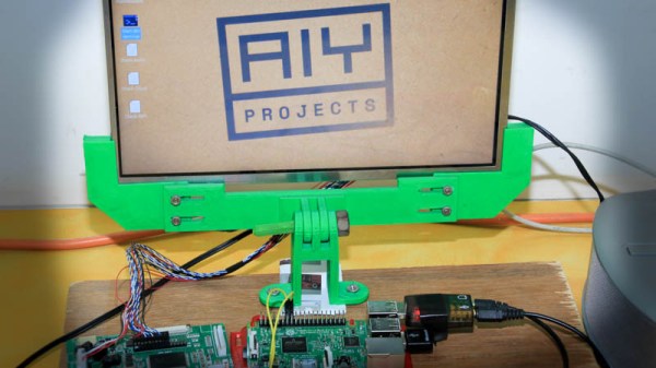
In this writeup, I layout the DIY version of the AIY kit for everyone else who wants to talk to a cardboard box. I take a closer look at the free kit, take it apart, put it together and replace it with DIY magic. To make things more convenient, I also designed an enclosure that you can 3D print to complete the kit. Lets get started.
One common complaint we hear from most new KiCAD users relates to schematic and footprint libraries. The trick is to use just one schematic symbol and footprint library each with your project. This way any changes to the default schematic libraries will not affect your project and it will be easy to share your project with others without breaking it. I’ve spent some time refining this technique and I’ll walk you through the process in this article.
We have covered KiCAD (as well as other) Electronic Design Automation (EDA) tools several times in the past. [Brian Benchoff] did a whole series on building a project from start to finish using all the various EDA packages he could lay his hands on. No CAD or EDA software is perfect, and a user has to learn to get to grips with the idiosyncrasies of whichever program they decide to use. This usually leads to a lot of cussing and hair pulling during the initial stages when one can’t figure out “How the hell do I do that?”, especially from new converts who are used to doing things differently.
Read on to learn the best practices to use when using KiCAD and its library management.
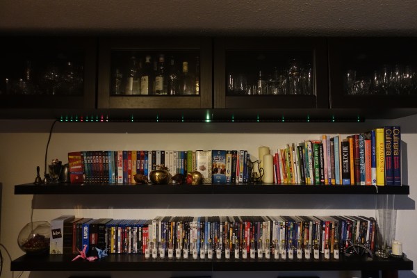
We love custom clocks here at Hackaday, and are always thrilled to see each inventive means of time-keeping. In a seldom-seen take on the familiar device, the [Bastel Brothers]’s LED Strip Clock’s sleek profile finds itself in good company.
The clock is a two-metre strip of 60 LEDs; every minute past the current hour corresponds to one lit LED, every fifth LED is turned to red in order to make reading minutes easier. So 3 red LEDs +3 green LEDs=18 minutes, with the hour marked by a third color. Sounds complex, but the [Brothers] are quick to say you get used to it quickly, especially when the 6 o’clock LED is centered at some noticeable object or feature.
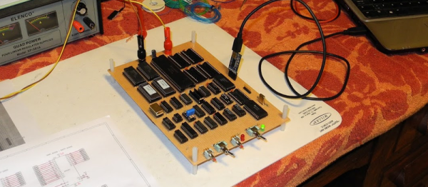
[Jeff Tranter] has done a number of retrocomputing projects. But he wanted to tackle something more substantial. So he set out to build a 68000-based single board computer called the TS2 that he found in a textbook. He’s documented it in a series of blog posts (about 30 posts, by our count) and a video that you can see below.
The 68000 had a very rational architecture for its day. A flat memory space was refreshing compared to other similar processors, and the asynchronous bus made hardware design easier, too. While most CPUs of the era assumed bus devices could perform their service in a fixed amount of time, the 68000 used a handshake with devices to allow them to take the time they needed. Most other CPUs had to provide a mechanism for a slow device to stall the bus which was complicated and, in many cases, less efficient.
Autodesk has announced that EAGLE is now only available for purchase as a subscription. Previous, users purchased EAGLE once, and used the software indefinitely (often for years) before deciding to move to a new version with another one-time purchase. Now, they’ll be paying Autodesk on a monthly or yearly basis.
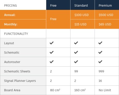
Lets break down the costs. Before Autodesk purchased EAGLE from CadSoft, a Standard license would run you $69, paid once. The next level up was Premium, at $820, paid once. The new pricing tiers from Autodesk are a bit different. Standard will cost $15/month or $100/year, and gives similar functionality to the old Premium level, but with only 2 signal layers. If you need more layers, or more than 160 cm^2 of board space, you’ll need the new Premium level, at $65/month or $500/year.
New Pricing Table for EAGLE
This is a bad deal for the pocket book of many users. If you could have made do with the old Standard option, you’re now paying $100/year instead of the one-time $69 payment. If you need more space or layers, you’ll likely be up to $500/year. Autodesk also killed the lower cost options for non-commercial use, what used to be a $169 version that was positioned for hobbyists.
The free version still exists, but for anyone using Eagle for commercial purposes (from Tindie sellers to engineering firms) this is a big change. Even if you agree with the new pricing, a subscription model means you never actually own the software. This model will require licensing software that needs to phone home periodically and can be killed remotely. If you need to look back at a design a few years from now, you better hope that your subscription is valid, that Autodesk is still running the license server, and that you have an active internet connection.
On the flip side of the coin, we can assume that Eagle was sold partly because the existing pricing model wasn’t doing all it should. Autodesk is justifying these changes with a promise of more frequent updates and features which will be included in all subscriptions. But sadly, Autodesk couldn’t admit that the new pricing has downsides for users:
“We know it’s not easy paying a lump sum for software updates every few years. It can be hard on your budget, and you never know when you need to have funds ready for the next upgrade.”
In their press release, they claim the move is only good for customers. Their marketing speak even makes the cliche comparison to the price of a coffee every day. Seriously.
[Garrett Mace] summarized his view on this nicely on Twitter: “previously paid $1591.21 for 88 months == $18.08/mo. Moving to $65/mo? KICAD looks better.”
We agree [Garrett]. KiCad has been improving steadily in the past years, and now is definitely a good time for EAGLE users to consider it before signing on to the Autodesk Subscription Plan™.
KiCad is the premiere open source electronics design automation suite. It’s used by professionals and amateurs alike to design circuits and layout out printed circuit boards. In recent years we’ve seen some incredible features added to KiCad like an improved 3D viewer and push-and-shove routing. This Friday at 10 am PST, join in a Hack Chat with KiCad lead developer [Wayne Stambaugh] to talk about recent improvements and what the team has planned for KiCad in the future.
[Wayne] has been an electronics engineer for over 30 years with a wide range of experience in analog and digital hardware design and embedded and application software design. He started hacking on KiCad ten years ago when the project was first opened to public development and a little over two years ago became the project leader. This is an excellent opportunity to learn how the development team works, what their current goals are, and to talk all things KiCad.
Also on Friday, taking place just an hour before the KiCad chat, is a Tindie Hack Chat. All are welcome as the 9:00 am PST discussion gets under way. Discussion will focus on all aspects of selling unique hardware on Tindie.
Here’s How to Take Part:
Buttons to join the project and enter Hack Chat
Hack Chat are live community events that take place in the Hackaday.io Hack Chat group messaging. Visit that page (make sure you are logged in) and look for the “Join this Project Button” in the upper right. Once you are part of the project, that button will change to “Team Messaging” which takes you to the Hack Chat.
You don’t have to wait for Friday, join Hack Chat whenever you like and see what the community is currently talking about.
Join Us Next Week Too for CircuitPython
Block out your calendar for noon PST on Friday the 27th for next week’s Hack Chat. Joining us are Adafruit’s Ladyada, Tony DiCola, and Scott Shawcoft. They’ll be leading a discussion about CircuitPython Beta, Adafruits new extension to MicroPython that adds SAMD21 support and other enhancements.
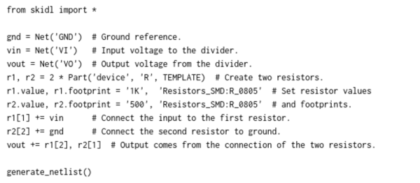
SKiDL is very, very cool. It’s a bit of Python code that outputs a circuit netlist for KiCAD.
Why is this cool? If you design a PCB in KiCAD, you go through three steps: draw the schematic, assign footprints to the symbolic parts, and then place them. The netlist ties all of these phases together: it’s a list of which parts are connected to which, the output of schematic capture and the input for layout. The ability to generate this programmatically should be useful.
For instance, you could write a filter circuit generator that would take the order, cutoff, and type of filter as inputs, and give you a spec’ed netlist as output. Bam! In your next design, when you need a different filter, you just change a couple of variables. Writing your circuits as code would make arranging the little sub-circuits modular and flexible, like functions in code.
At the very least, it’s an interesting alternative to the mouse, click, drag, click paradigm that currently dominates the schematic capture phase. Just as some of you like OpenSCAD for 3D modelling, some of you will like SKiDL for circuit design.
We’ve become so accustomed to the circuit diagram as the means of thinking about circuits that we’re not sure that we can ever give up the visual representation entirely. Maybe designing with SKiDL will be like sketching out block diagrams, where each block is a bit of Python code that generates a circuit module? Who knows? All we know is that it sounds potentially interesting, and that it’ll certainly be mind-expanding to give it a try.
Give it a shot and leave feedback down in the comments!