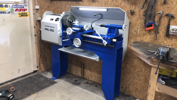
Like many budget machinists, the delightfully optimistically named [We Can Do That Better] had trouble with some of the finer controls on his import mini-lathe. But rather than suffer through it, he chose to rectify the machine’s shortcomings and in the process, teach everyone a bunch of great tips.
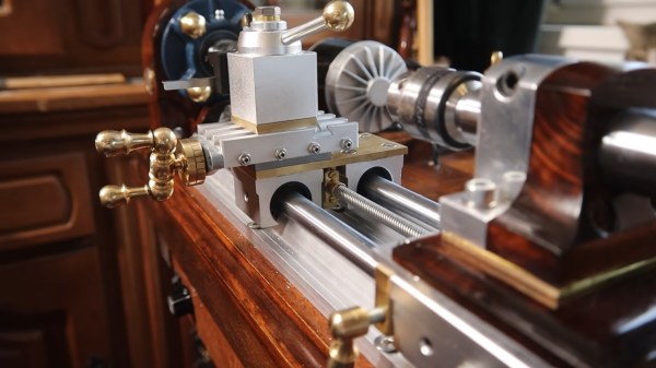
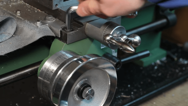
[We Can Do That Better]’s lathe retrofit focused on the carriage handwheel, which appears to lack proper bearings and wobbles around in a most imprecise manner. On top of that, the gearing of the drive made for an unsatisfying 19 mm of carriage travel per revolution of the handwheel. A single gear change made that an even 20 mm per rev, which when coupled with a calibrated and indexed handwheel ring greatly simplifies carriage travel measurements.
While the end result of the build is pretty great in its own right, for our money the best part of the video is its rich collection of machinist’s tips. The use of a wooden dowel and a printed paper template to stand in for a proper dividing head was brilliant, as was using the tailstock of the lathe to drive an engraving tool to cut the index lines. We’ve seen the use of a Dremel tool mounted to the toolpost to stand in for a milling machine before, but it’s always nice to see that trick used. And the mechanism for locking the dial to the handwheel was really clever, too.
Considering a mini-lathe? As encouraging as [We Can Do That Better]’s experience may be, it might be wise to take a deep dive into the pros and cons of such a machine.
Continue reading “Improving A Mini-Lathe With A Few Clever Hacks”