Gigantic Liquid Crystal Display Is Like A Giant Calculator

Some say he turns on his soldering iron by saying, “Flame on!.” He deadbug solders – QFP packages. All we know is he’s called [stig] and he sent in an awesome an awesome video of a new display at the Nature Research Center in Raleigh, North Carolina. It’s a 10 foot by 90 foot LCD display that uses 6 inch square glass panels containing the same liquid crystals you’d find in a calculator.

The display/installation is called Patterned by Nature and is built using 3600 pieces of LCD privacy glass. When a voltage is applied to the glass it changes from clear to opaque. While this technology has been around for decades (just look at your calculator), only in the last few years has LCD privacy glass come down in price to make a project like this economical.

The gigantic display was created in part by Sosolimited, an art studio who has made a similar project before. The display hanging in the atrium of the Raleigh Nature Research Center is amazingly efficient for its size  drawing only 75 watts.

If you’d like to try your hand at a similar build, we wish you luck; this LCD glass is still somewhat expensive but perhaps in a few years the price will come down enough that we can play Tetris on the side of a building.

Continue reading “Gigantic Liquid Crystal Display Is Like A Giant Calculator”

Reverse Engineering A Nokia LCD

LCD displays taken from old Nokia phones have been a staple of the hardware makers for years now, so we’re very happy to see [Andy] reverse engineering a full color QVGA display so we can move our grayscale projects over to a full-color display.

The screen in a Nokia 2730, 5000, and 7100 cell phone is a wonder of technology – its 18-bit color with a very high-resolution piqued [Andy]’s interest. He bought a second-hand Nokia 2730 off of eBay and started taking it apart. After checking out the schematics for the phone, [Andy] had a few breakout boards made; especially useful since he found a few connectors as well.

With a great deal of Googling, [Andy] found another lost soul who successfully broke into a similar LCD display and discovered it was command-compatible with a Magnachip LCD controller. The only way forward was to send a few of these commands over to the display and watch what happens.

[Andy] managed get pixels drawn on the screen, and found a few interesting features: hardware scrolling is enabled, as is changing between portrait or landscape orientations. From a second-hand phone on eBay, [Andy] now has a very nice QVGA display. We’re calling this a win, but you can judge the video after the break for yourself.

Continue reading “Reverse Engineering A Nokia LCD”

WAV Playback With An ATmega32

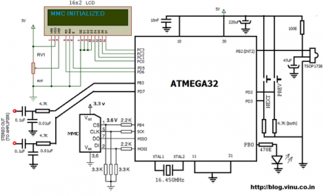
[Vinod Stanur] just finished another hobby project by building a WAV audio player using a microcontroller. He had started development a while back using a PIC microcontroller. But the chip he was using didn’t have enough SRAM to allocate as a playback buffer. When he got his hands on an ATmega32 his mind turned back to the project and he saw it through to the end.

He takes advantage of what he learned on several earlier builds. He’s using a TV remote as input, just like his Snake game did. Storage is provided by an MMC card, a trick he perfected with this voice recorder project. Instead of using a FAT library, he uses his own code to read the linked-list (File Allocation Table) for sector addresses, then he parses the WAV header and processes the file accordingly.

Playback uses two 512 byte buffers. One is feeding the output while the other is being populated from the memory card. When the output buffer is exhausted the two are swapped and the process continues. You’ll find [Vinod’s] demo of the project after the break.

Continue reading “WAV Playback With An ATmega32”

Up Your FPGA Game By Learning From This LCD Control Prototype

[Cesar] recently got a PSP display up and running with his FPGA development board. That’s a nice project, but what we really like is that he set aside a lot of time to show how it’s done every step of the way. This isn’t just a tutorial on that particular screen, but an overview of the skill set needed to get any piece of hardware working.

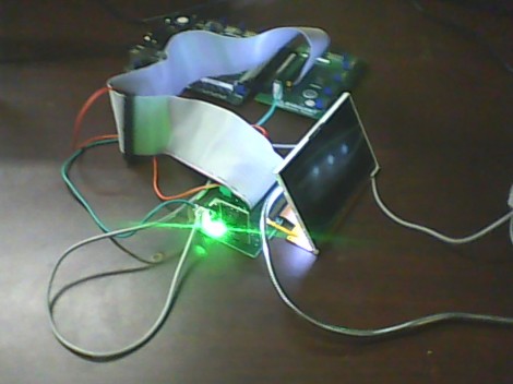
The screen itself is a Sharp LQ043T3DX02; a 480×272 TFT display with 16 million colors. Not bad for your project but when you start looking into the control scheme this isn’t going to be like using a Nokia screen with an Arduino. It takes twenty pins to control it; Red, green, and blue take sixteen pins, four pins are used for control, the rest are CK, DISP, Hsync, Vsync.

Wisely, [Cesar] designs his own interface board which includes the connector for the ribbon cable. It also has drivers for the screen’s backlight and supplies power to the device. With hardware setup complete he digs into the datasheets. We just love it that he details how to get the information you’re looking for out of this document, and shows his method of turning that first into a flow chart and then into code for the FPGA.

Who Couldn’t Use A Little More Screen Space?

Text LCD’s are handy for any occasion, a printer port on your PC is also darn handy as well. Mix together and add in a splash of linux and you get a very handy Linux device driver for a 16×2 LCD connected to the parallel port.

Electrically the LCD is wired up in a typical 4 bit mode, this allows the parallel port to use its 8 bit data register to write data, but also control the Register Select and Enable pins. Next is to make a module for linux to use, it seems like pretty standard fair for this type of screen.

Make the driver, insert the module so it can be loaded, and add a node so you know where to find it later, and your only an “echo Hello > /dev/my_lcd” away from finding all sorts of creative uses for your new external display.

Build Your Own 4-channel Logic Analyzer

If you’re just getting into hobby electronics chances are there are lots of tools you’d like to get you hands on but can’t yet justify the purchases. Why not build some of the simpler ones? Here’s a great example of a 4-channel logic analyzer that can be your next project and will add to your arsenal for future endeavors.

As you can see, [Vassilis’] creation uses a cellphone-sized LCD screen as the output. It is powered by four rechargeable batteries and driven by an ATmega8 microcontroller. He’s designed the tool without power regulation, relying on the ATmega’s rather wide range of operating voltages, and a few diodes to step down that voltage for the LCD screen.

As you can see in the clip after the break, alligator leads can be used to connect the test circuit to the inputs (don’t forget the ground reference!). Thee buttons at the bottom let you navigate the captured data by panning and zooming. Perhaps the best design feature is the single-sided circuit board which should be quite easy to reproduce at home.

Continue reading “Build Your Own 4-channel Logic Analyzer”

Using A Touch Screen With An STM32 Microcontroller

[Andy Brown] has been working on a series of tutorials revolving around the STM32 processor family. He’s using the STM32plus development board, with an STM32F1 ARM Cortex M3 processor to drive a couple of different full color graphic LCD screens. His latest installment shows how to read from the touch screen included with both displays.

After the break we’ve embedded the video from which this screenshot was taken. As an example, [Andy] has programmed a painting program to show off what the touchscreen overlay is capable of. It starts off with the calibration routine we’re all familiar with, then drops to this screen with a virtual control panel and blank canvas.

This hardware uses the Texas Instruments ADS7843 controller, which [Andy] says is extremely common and that several other manufacturers use the same communications protocols. He discusses how to communicate with the controller, and how to incorporate the data into your program. Included is an open source library which you can use in your own projects.

Continue reading “Using A Touch Screen With An STM32 Microcontroller”