BeagleBone Powers This Networked LED Marquee

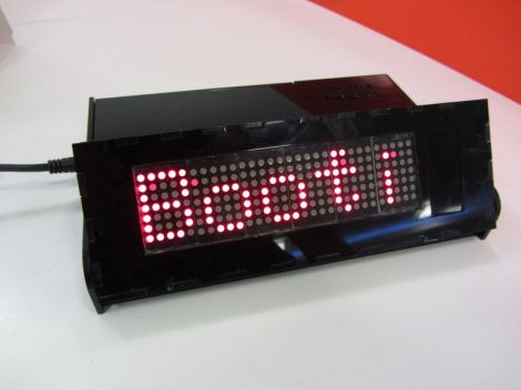
[Mahmut] calls this project SmartBox. It’s a BeagleBone controlled LED marquee which can pull down information off of the Internet.

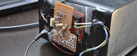
The project started with the display itself. [Mahmut] used six 5×7 LED modules to populate a circuit board he produced himself. The low side of the modules is controlled by some MBI5026 constant current drivers, with PNP transistors on the high side. The display connects to the BeagleBone ARM board using a couple of IDC ribbon cable connectors. With that up and running he started working on the enclosure. The display board was modeled in Google SketchUp to ensure that the case design would fit it properly. The laser cut acrylic case is in two parts, the base holds the driver electronics, with a hinged section for adjusting the angle of the marquee.

So far there are a few different connectivity features which are shown off in the clip after the break. The BeagleBone has the ability to pull down Twitter feeds, notify about incoming email, and scroll messages.

Continue reading “BeagleBone Powers This Networked LED Marquee”

Hackaday Links: October 31st, 2012

LED Marquee Pumpkin

Here’s an LED marquee as the mouth of a Jack-o’-lantern which [Mike Skoczen] made. This comes hot on the heels of that playable Tetris Pumpkin. [Thanks Jacob]

Arduino-powered robot costume

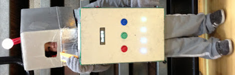
This is a sideways view of the Arduino-powered costume [Dan] and his wife made for their son. It has lights, buttons, a character display, and makes noise.

Cylon Centurion from a pumpkin

Stuck inside because of the hurricane, [Shawn] and his girlfriend carved this Cylon Centurion pumpkin complete with lights and sound.

8×8 LED costume ‘face’

[Matthew] built this helmet which features an 8×8 RGB LED matrix as the face. He calls it the digital reaper. You can see him testing the electronics in this clip.

Makerspace costume roundup

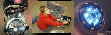
[Jeff] wrote in to tell us about the Halloween preparations at the Port City Makerspace in Portsmouth, New Hampshire. Here we have a Ghost Busters Proton Pack, weeping angel wings from Dr. Who, and an Arc Reactor from Ironman.

Bluetooth Control For Your DSLR Or Just About Any Other IR Operated Device

Just the other day we were reading a Reddit thread asking about how to control a television with a smartphone. The conversation started by talking about adding an IR LED to the phone.  Then it was suggested that there should be standalone Bluetooth devices that convert commands to IR, and came around to the ideas that TV’s should ship with native Bluetooth hardware. We couldn’t agree more but we’re also not about to replace our TV just for this option. That’s why we were delighted to find this project waiting on our tip line. It’s a method of controlling a camera shutter from a smartphone using Bluetooth. But the technique will work for any device which uses an infrared remote control.

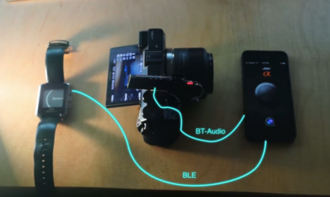
The video after the break shows two different devices controlling the camera shutter. As you can see in the diagram above, the iPhone is the master controller, connecting to a Bluetooth headset mounted on the camera. That headset was altered to feed the speaker connections into an IR LED pointed at the camera’s receiver. The iPhone plays an encoded audio track matching the IR remote command, resulting in the properly formatted message flashing on the LED. The watch doesn’t have the ability to playback audio, but it can send a message to the phone, which then plays the proper audio track through the headset.

Continue reading “Bluetooth Control For Your DSLR Or Just About Any Other IR Operated Device”

A PIC Powered Pair Of Electronic Dice

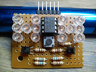
[Timothy] is honing his microcontroller skills with this electronic dice project. In addition to giving him an opportunity to work on some code, the use of an 8-pin chip provides a design challenge for driving the twelve pips and providing a user input.

The project started off with some $4 strings of LED Christmas lights. He promptly disassembled the strands, each yielding 100 LEDs. The microcontroller he chose to work with is a PIC 12F629. It’s DIP8 package provides six I/O pins to work with. When examined closely you will find that the pips on a die are always present in pairs with the exception of the center pip. This means that only four pins are needed to drive one die. You can see a pair of transistors above; one is a PNP, the other an NPN. These are both driven from the same uC line, which toggles between the pair of die. This accounts for 5 of the available pins, with the sixth monitoring the push button.

Electronic Demon Costume Is Surprisingly Unnerving

[Phil] over at Adafruit crashed last Sunday’s Show and Tell with an amazing demon costume that includes a voice changer and animated LED matrices for The Eyes and mouth. He just posted how he built this costume, but you’ve really got to Watch the video to see how awesome this build is.

Every demon needs a scary voice, so [Phil] repurposed his Arduino-based voice changer for this build. By being able to adjust the pitch of the demon’s voice with the turn of a knob, [Phil] goes from growling from the pits of hell to a demon with just a slightly annoying voice.

The Eyes make use of the Adafruit I2C LED matrix backpack. The eyes are wired to the same I2C address to prevent derping, but the three red mouth LED matrices are capable of displaying anything that fits on an 8×24 LED matrix.

The electronic portion of this build is mounted to a piece of plexiglas, which is in turn mounted to a mask [Phil] picked up from a craft store. Not really the best option considering the Halloween stores are now open for the year, but it does its job.

A Morphsuit – a spandex bodysuit – completes the build along with a few demon wings and horns. During Adafruit’s Show and Tell, [Phil] had electronic parts scattered all over his desk. To turn this into a costume, he’ll be mounting a small battery-powered speaker in a chest piece and stuffing all the electronics in a fanny pack.

It’s a very, very cool build that really steps up the game for Arduino-powered costumes. Check out the video after the break.

Continue reading “Electronic Demon Costume Is Surprisingly Unnerving”

Graphing The Efficiencies Of LED Light Strips

After adding a few LED light strips above his desk, [Bogdan] was impressed with the results. They’re bright, look awesome, and exude a hacker aesthetic. Wanting to expand his LED strip installation, [Bogdan] decided to see if these inexpensive LED strips were actually less expensive in the long run than regular incandescent bulbs. The results were surprising, and we’ve got to give [Bogdan] a hand for his testing methodology.

[Bogdan]’s test rig consists of a 15 cm piece of the LED strip left over from his previous installation. A Taos TSL2550 ambient light sensor is installed in a light-proof box along with the LED strip, and an AVR microcontroller writes the light level from the sensor and an ADC count (to get the current draw) of the rig every 6 hours.

After 700 hours, [Bogdan]’s testing rig shows some surprising results. The light level has decreased about 12%, meaning the efficiency of his LED strip is decreasing. As for projecting when his LEDs will reach the end of their useful life, [Bogdan] predicts after 2200 hours (about 3 months), the LED strip will have dropped to 70% of their original brightness.

Comparing his LED strip against traditional incandescent bulbs – including the price paid for the LED strip, the cost of powering both the bulb and the strip, the cost of the power supply, and the time involved in changing out a LED strip, [Bogdan] calculates it will take 2800 hours before cheap LEDs are a cost-effective replacement for bulbs. With a useful life 600 hours less than that, [Bogdan] figures replacing your workshop lighting with LED strips – inexpensive though they are – isn’t an efficient way to spend money.

Of course with any study in the efficiency of new technology there are bound to be some conflating factors. We’re thinking [Bogdan] did a pretty good job at gauging the efficiency of LED strips here, but we would like to see some data from some more expensive and hopefully more efficient LED strips.

4096 LEDs Means The Biggest LED Cube Ever

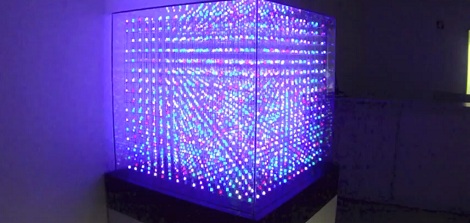
Adaptive Computing, a cloud management and high performance computing outfit in Utah, needed something really cool to bring to their trade shows. Something that makes order out of chaos, and demonstrates their attention to detail in the midst of miles of wiring. They decided building the largest non-commercial LED cube would be a good project, and thus the 16x16x16 All Spark Cube was born.

The All Spark Cube was constructed using 10 mm RGB LEDs wired together with three-foot lengths of 16 ga pre-tinned copper wire. In this video, [Kevin] shows off the process of constructing a single row; first the LEDs are placed in a jig, the leads are bent down, and a bus wire is soldered to 16 individual anodes per row.

The hardware for the build uses 16 Arduino Megas with a custom-made shield powering a 16×16 LED grid. The custom shields provide the 24V for the LEDs, 5V for the ‘duino, The Arduino boards communicate to each other through an RS485 connection, and the entire cube is connected to a computer through an RS232 serial connection.

The software is, admittedly, still a little janky. [Spencer] and [Thomas], the Adaptive Computing volunteers that are working on the control system, are still having a few problems getting logos and animations to display. They have managed to create a control app to draw individual pixels, as seen after the break.

Not bad for nearly a mile of wire and a summer’s worth of work, huh?

Continue reading “4096 LEDs Means The Biggest LED Cube Ever”