juke-footwell-lighting

DIY Car Lighting Illuminates Areas The Designers Overlooked

[Dave] just can’t seem to get enough of modifying his new car. Where he lives, it’s typically dark on his ride home from work and he finds himself dropping things on the floor of his car all too often. Nissan decided not to include lighting in the Juke’s foot well or glove box, so [Dave] decided that he needed to rectify the situation.

As you might have noticed by his previous tinkering, [Dave] is a big fan of LEDs and ATTiny microcontrollers. He added some Lego-supported LEDs to the driver and passenger side foot wells, installing an additional light in the glove box while he was at it.

The Juke had a couple of usable blank spots on the dashboard, so [Dave] installed a pair of capacitive touch sensors and a small switch into one of the open slots. When touched, the top-most capacitive pin pair ramps up the foot well lights, while the lower pair turns on the LEDs in the glove box. The switch at the bottom is used to toggle on a light in the back seat which he installed a while back.

It’s a simple addition, but it makes all the difference when he is hunting around on the floor in the dark. We are a bit surprised by how many amenities are missing from the Juke, but tweaking them to his liking seems to keep [Dave] happily occupied.

Continue reading to see a short demo video of his interior lights in action.

Continue reading “DIY Car Lighting Illuminates Areas The Designers Overlooked”

This Giant Hand Made LED Matrix Must Be Ours!

giant-led-matrix

[Martin] wrote in to share a project his company has been working on for some time, a gigantic 1470 pixel LED wall. The group provides lighting for clubs, parties, etc, and their hand-built LED matrix is always certain to be the hit of the show.

The amazing matrix was designed from the ground up and built by hand in [Martin’s] living room. They designed small 32x32mm “pixel” boards, each of which features 6 PLCC6 RGB LEDs driven by a single WS2801 LED controller. The PCBs were populated by hand and each one was reflowed in a small pizza oven that [Martin] owns. After the pixels were completed, they were attached to aluminum bar and combined to build thirty 70x70cm frames which are connected together to form a giant matrix.

As you can see in the collection of videos below, the display is very impressive. We just hope that they will be compelled to release the schematics for their boards so that we can build one of these in the office.

Continue reading “This Giant Hand Made LED Matrix Must Be Ours!”

Monitoring Batch Jobs The Cylon Way With Python And A Parallel Port

parallel-port-trigger

If you happen to do a lot of video encoding, you know that your computer can really drag while the process is carried out. Our own [Mike Szczys] transcodes videos at home fairly often, and because the process is automated, he doesn’t always know if a conversion is taking place in the background.

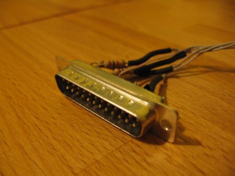
He has been tinkering with Larson Scanners recently and thought he could put everything he’s learned along the way to good use by using the scanner as a “busy” indicator for his PC. He hooked the scanner up to the computer’s parallel port, and took a few minutes to bang out some Python code that would alert him when his PC was busy.

He set his notifier script to launch along with FFMPEG, whenever his MythTV setup had something ready to convert. The Python script drives a pin on the parallel port high, triggering the Larson Scanner’s animation. Every minute, the script checks the status of FFMPEG and continues to hold the pin high until the application exits. Once the conversion is done, the scanner goes back to sleep, letting [Mike] know that the coast is clear.

Check out the video below the break to see his parallel port trigger in action.

Continue reading “Monitoring Batch Jobs The Cylon Way With Python And A Parallel Port”

DIY LED Photography Lights

led-light-box

[Markus] had been drooling over some LED panels to use as a soft light source for photography, but being a hobbyist, he didn’t want to spend a ton of money to buy them. He figured that he had enough electronics know-how to build his own panels, while saving a boatload of cash in the process.

He hoped to keep the total cost under £100, so along with new items like LED light strips, he would have to use some stuff he had sitting around, like the metal cooking containers that make up the body of the lights. While originally planned for use in a different project, it turns out that the cooking containers were ideal for his lighting setup, since they are both durable and great heatsink material.

The remainder of the build is pretty straightforward. [Markus] used a pre-made LED dimmer to control the panel’s brightness, along with some tinted plexiglas to diffuse the light while bringing the color temperature into a more usable range.

While he missed his £100 mark, the lights look great – we just might have to build a few of them ourselves.

ColorNode: A Drop-in GE Color Effects LED Controller

colornode-ge-color-effects-controller

[Paul] was looking to spice up his holiday decorations this year, so he picked up some GE Color Effects lights and started hacking away.

We’ve already seen how hacker-friendly these LED bulbs are, which is why [Paul] decided to give them a try. His ultimate goal was to synchronize several sets of lights from one location, which would unfortunately require that he run wires from his control board to each of the strings.

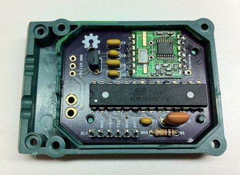
He then decided to go a different route, and build his own control board that would work as a drop-in replacement for GE’s controller circuitry. He wanted to retain the wireless control aspect of the lights, so he picked up some RFM12B wireless modules which happen to be well-supported by the folks at JeeLabs.

He modified their JeeNode board design to fit it in the Color Effects electronics enclosure, paring it back to the minimum components necessary to control his lights.

The hardware side of the ColorNode is complete, but the software is a work in progress. [Paul] says that once he gets things wrapped up, he will make the code available on his site.

Controlling Shift Registers Via SPI

Hack a Day’s very own (and very prolific contributor) [Mike Szczys] put up a great tutorial on how to drive shift registers with an SPI interface.

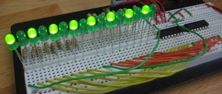
[Mike]’s earlier tutorial of the 595 shift register goes through the functions of a shift register pin by pin. In a 595, bits for each position in the register are sent over one at a time. Most microprocessors have an Serial Peripheral Interface, and using an SPI bus means a lot less mucking about.

An ATmega168 was used for this build, although most Atmel chips can be made to work as an SPI master device. There are just three wires connecting the microcontroller to the shift register – SER, SRCLK, and RCLK. Like any other shift register setup, the build can be expanded by connecting the QH’ pin of the first 595 to the SER pin of the second.

[Mike] graciously made all the code for his build available. The video after the break is a 16-bit binary counter, a good stopping point before [Mike] rebuilds his Larson scanner/Cylon/Kitt, moving away from a PWM-based build to a register-based one.

Continue reading “Controlling Shift Registers Via SPI”

Shutter Trigger Remote With Some Nice Design Considerations

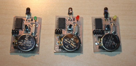
Here are the guts of [Lukasz’s] infrared camera remote control. He based it off of an existing design, but looked for places where improvements could be made. He felt the ATtiny2313 was a bit wasteful in this case. But further investigation led him to see why it was chosen. If you were to drop down to an ATtiny13 the ability to connect a crystal oscillator is lost (that chip only offers a 1-pin clock signal input) and the internal RC oscillator isn’t quite up to his standards for reliable IR communications.

Instead of driving the IR LED directly from an AVR pin he used a transistor in hopes that it will allow the maximum current to flow through the diode when in use. We’re not sure if it’s necessary, but we can see how it makes sense. Power is received from an unregulated 3 volt coin cell, so maybe as that voltage drops over time this will come into play.

Speaking of that coin cell, battery life is a concern here. [Lukasz] is using the sleep functions of the AVR after three seconds of use. This should keep the cell alive for quite a long time. But his 0 volt measurement is an anomaly with the multimeter he’s using. To get a precise measurement for tiny current flow you need extra equipment, like [Dave Jones’] uCurrent adapter.

The schematic for this Canon camera compatible project is only provided in Eagle format so we’ve embedded an image of it after the break for your convenience. You should have no problem making this work with a Nikon if you swap out some of the code from the TV-B-Gone shutter release we saw on Thursday.

Continue reading “Shutter Trigger Remote With Some Nice Design Considerations”