[Isaac] sent in his mashup build of a LED cube combined with a graphic EQ meter. The build is fairly simple and from the video we can tell that his build would be a great installation in a dubstep venue. While it’s not the 9x9x9 cube possible with some judicious coding we think it’s a very fitting display for the intended purpose.
led1362 Articles
A Pill Reminder Box To Be Proud Of
Not satisfied with the traditional daily pill boxes, [Ryan] set out to build his own. According to his article, these particular pills had to be taken every three days, and he wanted a solution that required “zero effort.” Although one might question whether his solution actually took this amount of effort, the build came out very well.
The result is a box that reminds one to take a pill from one or two bottles using a blinking LED. When the pill bottle is picked up, consumption is assumed and the timer is reset. The main components consist of an Arduino, real time clock, and a battery backup. Additionally, two picture frames are used to form the project enclosure along with some LEDs and other assorted hardware to finish everything.
This project combines some basic electronics hacking and programming with a very nice looking cover. The results are a very clean looking build with a good write up. For another example of a well finished project with great pictures, check out this N64 portable build.
Guitar Becomes An Improved Color Organ
[Charles] wanted to put some LEDs in his guitar. He also wanted individual notes to output certain colors, but he couldn’t find any projects with tone-based algorithms to convert sound into colors. After about a year of work, his ColorChord guitar was born.
Unlike every other color organ build we’ve seen, the color of a note does not relate to the absolute pitch of the note. Instead, the colors are mapped within a musical key. A I chord will always be Yellow, a IV chord will always be purple, and a V chord will always be blue. Playing in the key of C will have the LEDs output yellow, purple, and blue for a C, F and G chord, respectively.
Using Binary Code Modulation To Control LED Brightness
Pulse Width Modulation is definitely the preferred method of dimming an LED with a microcontroller, but we were interested in hearing about a different method called Binary Code Modulation. BCM does the same thing as PWM, it turns the LED on and off very rapidly so that your eye cannot detect a flicker. The brightness level is a result of the average amount of time the LED is on versus when it is off. This is called duty cycle and although it can be the same percentage for both PWM and BCD, there is a fundamental difference.
While PWM usually uses a cyclical on/off cycle (30% on, 70% off, repeat) BCD uses a cumulative cycle. As you can see above, each successive bit of binary code carries double significance compared to the previous bit. Now just assign a duty cycle based on your precision, and have an interrupt fire for each bit of the counter. The graph above shows some highs and some lows combining to reach the target duty cycle. An interrupt is used for each bit, and pin changes are made in the service routine.
The benefit of this system is that it is scaleable without adding overhead. You’re already running the interrupts so servicing 8 or 128 LEDs doesn’t have vastly different needs as it would with PWM. The big downside is that the more bits of precision you use, the faster your processor must run so that the eye doesn’t detect the lengthy on or off cycles of the higher bits as visible flickering.
Thank you [Yetihehe] for tipping us off about a link that [Tomas Martinsen] left when commenting about an Arduino library for up to 768 PWM outputs.
Race Car POV LED Displays

Last year, when [Alex] was asked by his friend [Martin] to help him out with building some LED POV modules for a race car, his response was a enthusiastic “YES!”
[Martin’s] goal was to involve fans more deeply in the race, so he decided that the POV modules would carry messages from fans on-board, printing them in the night as the race cars screamed around the track. The pair started prototyping and testing a design, wrapping things up shortly before this year’s 24 hours of Nürburgring.
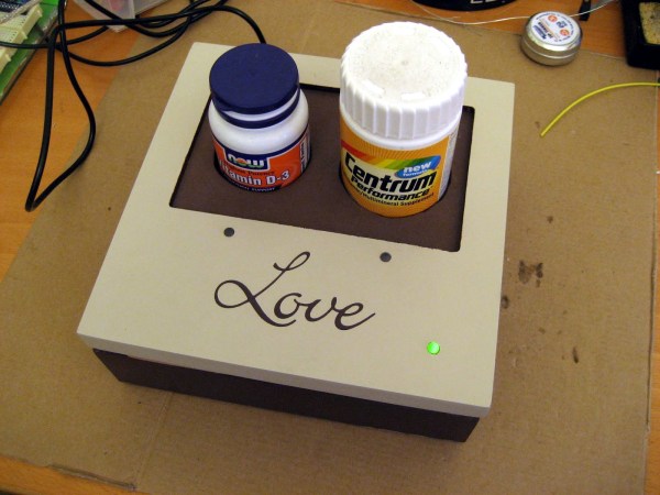
The modules consist of an Arduino-compatible AVR, a GPS module, a 16-LED light bar, and the circuitry for driving the LEDs. While most of the components are pretty standard fare, the we don’t often see a GPS sensor built into a POV display. [Alex] says that the sensor is used to calculate the speed of the cars, ensuring a uniform font size.
They took their LED displays to the 24 hours of Nürburgring, where they were invited by Audi to install the modules on a pair of R8 Le Mans race cars. As you can see by the pictures on his blog and Flickr set, the POV units worked out nicely without having to stretch the camera exposure times too far.
If you’ re interested to hear a bit more about how the displays were built, check out this entry in[Alex’s] blog, where he goes through some additional details.
Update:[Alex] pointed us to the videos!
Faux LED Scroller Using Phosphorescence

Hackaday reader [BGR] wrote in to share a video he put together showing off a cool “poor man’s LED scroller” that he built. Rather than build a huge array of LEDs, spending tons of time time wiring and programming, he decided to use only a handful of LEDs on a moving display instead.
The scroller is built upon a PIC16F887 microcontroller which resides on an EasyPIC6 dev board he borrowed for the project. The PIC controls a strip of eight bright white LEDs, which are used to write text on a long strip of phosphorescent paper that can be found at many printing supply outfits. The paper’s dispensing mechanism was cobbled together with parts from several sources, including a laser printer and VCR.
When he wants to display a message, he inputs text into a flash application he wrote. The app sends the LED byte values to his scroller via a separate serial proxy that talks to the pic over his computer’s COM port.
The effect is pretty slick, looking similar to a slow-moving diffused LED scroller. The messages disappear after about 5 minutes in a pitch black room, which is perfect, since he originally intended to use the device for displaying Twitter updates. He is already considering a second revision of the project, which he wants to mount on the wall – sounds great to us!
Be sure to swing by YouTube to see the video, or continue reading to watch it here.
Wearable Video Coat

[David Forbes] is no stranger to the weird and esoteric, so he created a color LED TV built into a lab coat. He plans on bringing it to Burning Man next month.
The RGB LEDs are mounted narrow flex boards, providing a 160×120 pixel NTSC display. Video processing is taken care of by an Xilinx FPGA that takes the YCrCb video feed from a video iPod and converts it into four separate RGB streams for the front, back, and the two sides. The requisite controls for brightness and color are on the shoulders.
Of course, the build wouldn’t be over-the-top without the ability to plug a Nintendo into a lab coat, so there’s an NTSC input on an RCA jack. Everything is powered by two 11.1 V, 5Ah radio-control LiPo battery packs that should power this for a while.
Check out a video of the LED lab coat below.
[youtube=http://www.youtube.com/watch?v=jtSm8Oom2n4&w=470]


