Largest LED Cube We’ve Ever Seen Is Still Only Half Complete

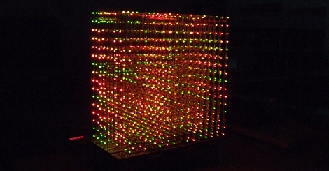
[Brendan Vercoelen] is a university student in New Zealand studying engineering. He says his recent gigantic LED cube build, “isn’t very serious” compared to other student projects, but that doesn’t mean it’s not impressive. The original plan for the build was a 16x16x16 tri-color LED cube. After realizing how much soldering that really was, [Brendan] scaled back his design a little to a 16x16x8 cubeoid, but the other half can be attached when the project is complete.

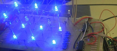
From the cost breakdown, [Brendan] only spent about $550 USD – far less expensive than we expected. The most expensive item was the 4,000+ Red-Green-Orange tri-color LEDs. The largest LED cubes (1, 2, 3) we’ve covered have maxed out at 8x8x8, or 512 total LEDS. Even though [Brendan]’s build is only half done, it’s still four times larger in volume than the largest LED cube we’ve seen.

The gauntlet has been thrown down. This is the one to beat, folks. Check out a video of the cube after the break.

Continue reading “Largest LED Cube We’ve Ever Seen Is Still Only Half Complete”
Control LED Lighting With An Old Stereo Receiver

stereo_controlled_home_lighting

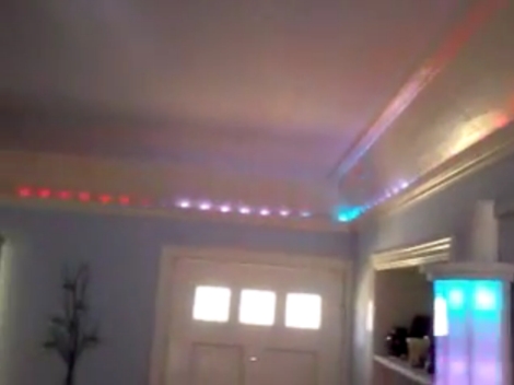
[Marklar] needed an IR receiver for a project he was working on, and his local electronics store was fresh out. He dug through his junk pile and found an old stereo receiver, so he decided to pull the IR module from it before tossing it out. Once he had it taken apart, he figured that he could utilize the wide array of electronic components he found inside, and set off to start a new project.

The control panel housed the components which interested him most of all. Using an Arduino, he was able to easily interface with the rotary encoders as well as the buttons, giving him a cheap and easy way to control his home lighting system. With a bit of programming, he was able to map lighting presets to various buttons, as well as use the rotary encoder to control the LEDs’ brightness and color. As an added bonus, he kept the IR receiver intact and can control his setup wirelessly as well.

Check out the video we have embedded below to see his scavenged control system at work.

[via HackedGadgets]

Continue reading “Control LED Lighting With An Old Stereo Receiver”

Lighted Shoe Ruffles — He’ll Never Step On Your Toes Again

Whether for fashion, emergency lighting, or just to make a statement, these lighted shoe clips make for a unique footwear accessory. [Becky Stern], who we’ve seen before hacking automatic knitting machines, tackles this quick lighted project.

The electronics are simple, two LEDs connected in parallel to a button battery by some conductive thread. The circuit is the same as an LED throwie, but she’s using a sewable battery holder. The ruffle is made by cutting out and folding several circles of fabric. We’re not too used to working with this building material and were glad to hear her tip on fusing the cut edges with a lighter. She’s also got a good tip about bending one LED lead in a square shape and the other in a round shape to keep track of the polarity. After sewing everything together and completing the circuit with the conductive thread [Becky] adds a paper clamp making this easy to use with any shoe. In fact, the guy’s don’t have to miss out on the fun as this could easily double as a boutineer.

Don’t miss [Becky’s] complete walk through video embedded after the break.

Continue reading “Lighted Shoe Ruffles — He’ll Never Step On Your Toes Again”

Using An LED Cube As An Audio Visualizer

[Isaac] sent in his mashup build of a LED cube combined with a graphic EQ meter. The build is fairly simple and from the video we can tell that his build would be a great installation in a dubstep venue. While it’s not the 9x9x9 cube possible with some judicious coding we think it’s a very fitting display for the intended purpose.

Continue reading “Using An LED Cube As An Audio Visualizer”

A Pill Reminder Box To Be Proud Of

Not satisfied with the traditional daily pill boxes, [Ryan] set out to build his own. According to his article, these particular pills had to be taken every three days, and he wanted a solution that required “zero effort.” Although one might question whether his solution actually took this amount of effort, the build came out very well.

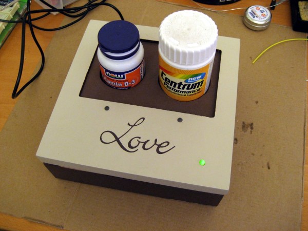
The result is a box that reminds one to take a pill from one or two bottles using a blinking LED. When the pill bottle is picked up, consumption is assumed and the timer is reset. The main components consist of an Arduino, real time clock, and a battery backup.  Additionally, two picture frames are used to form the project enclosure along with some LEDs and other assorted hardware to finish everything.

This project combines some basic electronics hacking and programming with a very nice looking cover. The results are a very clean looking build with a good write up. For another example of a well finished project with great pictures, check out this N64 portable build.

Guitar Becomes An Improved Color Organ

[Charles] wanted to put some LEDs in his guitar. He also wanted individual notes to output certain colors, but he couldn’t find any projects with tone-based algorithms to convert sound into colors. After about a year of work, his ColorChord guitar was born.

Unlike every other color organ build we’ve seen, the color of a note does not relate to the absolute pitch of the note. Instead, the colors are mapped within a musical key. A I chord will always be Yellow, a IV chord will always be purple, and a V chord will always be blue. Playing in the key of C will have the LEDs output yellow, purple, and blue for a C, F and G chord, respectively.

Continue reading “Guitar Becomes An Improved Color Organ”

Using Binary Code Modulation To Control LED Brightness

Pulse Width Modulation is definitely the preferred method of dimming an LED with a microcontroller, but we were interested in hearing about a different method called Binary Code Modulation. BCM does the same thing as PWM, it turns the LED on and off very rapidly so that your eye cannot detect a flicker. The brightness level is a result of the average amount of time the LED is on versus when it is off. This is called duty cycle and although it can be the same percentage for both PWM and BCD, there is a fundamental difference.

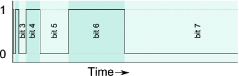
While PWM usually uses a cyclical on/off cycle (30% on, 70% off, repeat) BCD uses a cumulative cycle. As you can see above, each successive bit of binary code carries double significance compared to the previous bit. Now just assign a duty cycle based on your precision, and have an interrupt fire for each bit of the counter. The graph above shows some highs and some lows combining to reach the target duty cycle. An interrupt is used for each bit, and pin changes are made in the service routine.

The benefit of this system is that it is scaleable without adding overhead. You’re already running the interrupts so servicing 8 or 128 LEDs doesn’t have vastly different needs as it would with PWM. The big downside is that the more bits of precision you use, the faster your processor must run so that the eye doesn’t detect the lengthy on or off cycles of the higher bits as visible flickering.

Thank you [Yetihehe] for tipping us off about a link that [Tomas Martinsen] left when commenting about an Arduino library for up to 768 PWM outputs.