Retrotechtacular: A Very British MagLev

When we look back to the 1970s it is often in a light of somehow a time before technology, a time when analogue was still king, motor vehicles had carburettors, and telephones still had rotary dials.

In fact the decade had a keen sense of being on the threshold of an exciting future, one of supersonic air travel, and holidays in space. Some of the ideas that were mainstream in those heady days didn’t make it as far as the 1980s, but wouldn’t look out of place in 2018.

The unlikely setting for todays Retrotechtacular piece is the Bedford Levels, part of the huge area of reclaimed farmland in the east of England known collectively as the Fens. The Old Bedford River and the New Bedford River are two straight parallel artificial waterways that bisect the lower half of the Fens for over 20 miles, and carry the flood waters of the River Ouse towards the sea. They are several hundred years old, but next to the Old Bedford River at their southern end are a few concrete remains of a much newer structure from 1970. They are all that is left of a bold experiment to create Britain’s first full-sized magnetic levitating train, an experiment which succeeded in its aim and demonstrated its train at 170 miles per hour, but was eventually canceled as part of Government budget cuts.

A track consisting of several miles of concrete beams was constructed during 1970 alongside the Old Bedford River, and on it was placed a single prototype train. There was a hangar with a crane and gantry for removing the vehicle from the track, and a selection of support and maintenance vehicles. There was an electrical pick-up alongside the track from which the train could draw its power, and the track had a low level for the hangar before rising to a higher level for most of its length.

After cancellation the track was fairly swiftly demolished, but the train itself survived. It was first moved to Cranfield University as a technology exhibit, before in more recent years being moved to the Railworld exhibit at Peterborough where it can be viewed by the general public. The dream of a British MagLev wasn’t over, but the 1980s Birmingham Airport shuttle was hardly in the same class even if it does hold the honour of being the world’s first commercial MagLev.

We have two videos for you below the break, the first is a Cambridge Archaeology documentary on the system while the second is a contemporary account of its design and construction from Imperial College. We don’t take high-speed MagLevs on our travels in 2018, but they provide a fascinating glimpse of one possible future in which we might have.

It does make one wonder: will the test tracks for Hyperloop transportation break the mold and find mainstream use or will we find ourselves 50 years from now running a Retrotechtacular on abandoned, vacuum tubes?

Continue reading “Retrotechtacular: A Very British MagLev”

A Stepper Motor For Two Dimensions

We’ve all heard linear motors, like those propelling Maglev trains, described as “unrolled” versions of regular electric motors. The analogy is apt and helps to understand how a linear motor works, but it begs the question: what if we could unroll the stator in two dimensions instead of just one?

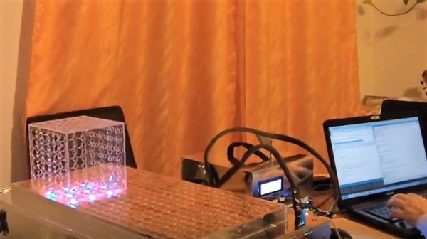
That’s the idea behind [BetaChecker’s] two-axis stepper motor, which looks like it has a lot of potential for some interesting applications. Build details are sparse, but from what we can gather from the videos and the Hackaday.io post, [BetaChecker] has created a platen of 288 hand-wound copper coils, each of which can be selectively controlled through a large number of L293 H-bridge chips and an Arduino Mega. A variety of sleds, each with neodymium magnets in the base, can be applied to the platen, and depending on how the coils are energized, the sled can move in either dimension. For vertical applications, it looks like some coils are used to hold the sled to the platen while others are used to propel it. There are RGB LEDs inside the bore of each coil, although their function beyond zazzle is unclear.

We’d love more details to gauge where this is going, but with better resolution, something like this could make a great 3D-printer bed. If one-dimensional movement is enough for you, though, check out this linear stepper motor that works on a similar principle.

Continue reading “A Stepper Motor For Two Dimensions”

A Cortex M4 Based Platform With ETH, USB, BT And Many On-board Peripherals

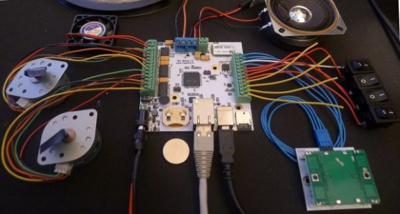
Here is a very time consuming project that I worked on during last summer: an ARM Cortex M4 based platform with plenty of communication interfaces and on-board peripherals. The particular project for which this board has been developed is not really HaD material (one of my father’s funny ideas) so I’ll only describe the platform itself. The microcontroller used in the project is the ATSAM4E16C from Atmel, which has 1Mbyte of flash and 128Kbytes of SRAM. It integrates an Ethernet MAC, a USB 2.0 Full-speed controller, a sophisticated Analog to Digital Converter and a Digital to Analog Converter (among others).

Here is a list of the different components present on the board so you can get a better idea of what the platform can do: a microphone with its amplifier, a capacitive touch sensor, two unipolar stepper motors controllers, two mosfets, a microSD card connector, a Bluetooth to serial bridge, a linear motor controller and finally a battery retainer for backup power. You can have a look at a simple demonstration video I made, embedded after the break. The firmware was made in C and uses the Atmel Software Framework. The project is obviously open hardware (Kicad) and open software.

Continue reading “A Cortex M4 Based Platform With ETH, USB, BT And Many On-board Peripherals”

Building A Linear Motor

linear-motor

We admit that this project doesn’t have very many details available, but it was just too neat for us to pass up. It’s a small linear motor which [ligonapProduktion] built after seeing a very brief description of a commercially available version.

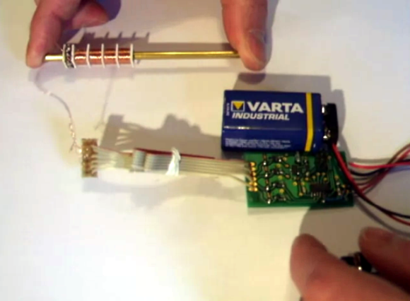
The video after the break shows him testing the motor. In this screenshot he’s holding the center shaft while the coil assembly moves back and forth. But it works with a stationary coil moving the rod as well. The motor is basically a modified solenoid. There are sixteen neodymium magnets inside the shaft. The set of four coils is driven by an ATtiny44. Just like a stepper motor, energizing the coils in the correct order pushes against the rare earth magnets creating motion.

We’re not sure if he has any use in mind for this build. For us we just like to see the concept in practice (we feel the same way about a homopolar motor build).

Continue reading “Building A Linear Motor”

Semi-automatic PCB Drill Press

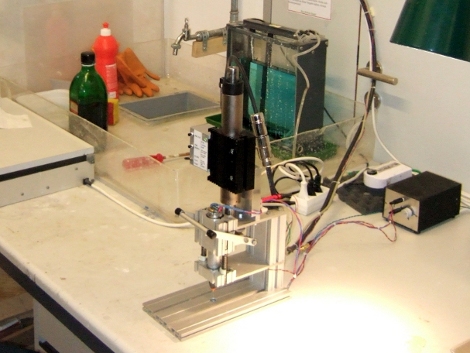
Kiss the days of breaking bits while drilling through-hole PCBs goodbye thanks to this semi-automatic drill press (translated). Now it’s not going to line up the bit with the exact location of the hole (that would make it a fully automatic drill press). This works by lining up the board manually, then stepping on a pedal to activate the plunging motion of the drill.

A linear motor is responsible for the smooth, accurate motion along the Z-axis. Many hobby setups use a Dremel drill press, or even rely on prayer-based systems such as doing it free-hand with a rotary tool or by using a piece of acrylic as a guide hole. The hobby drill press tends to have some play in it and free-handing with tiny bits that are as fragile as glass both result in far too many broken drill bits. In the video after the break you can see that the linear motion is perfectly plumb with the table of the device, preventing the movements that cause breakage. The addition of the pedal makes it easy to position the boards because you can use both hands.

Having a tool like this takes all of the frustration out of using through-hole parts.

Continue reading “Semi-automatic PCB Drill Press”