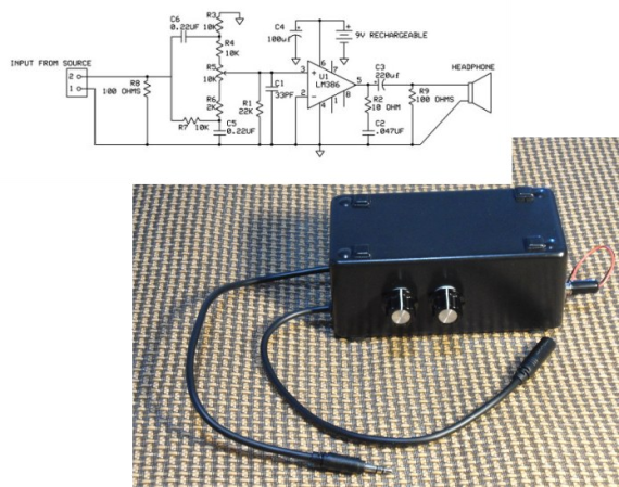
Crystal radios may be the simplest kind to make, but regenerative receivers are more practical and only a little more complicated. A recent design by [Selenium] is super simple because it uses a single LM386 audio amplifier IC.
You might be surprised that you can convert an audio amplifier to a receiver using just a handful of components (a variable capacitor, a coil, a handful of capacitors, and a speaker). However, [Selenium] realized he could subvert the gain and bypass pins to cause regeneration and wound up with a very simple receiver.
If you haven’t looked at regenerative receivers before, the principle is simple (and dates back to 1912). An oscillator is an amplifier that gets (theoretically) an infinite amount of gain at one particular frequency. A regenerative receiver is just an amplifier that is almost (but not quite) at the point of oscillation. This gives it very high frequency-specific gain and a measure of selectivity. You can also nudge the receiver just into oscillation to receive CW or SSB signals.
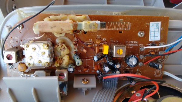
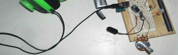
[Selenium] built his prototype on an old receiver chassis because it had the IC and the variable capacitor already in place. However, others have built successful copies on breadboards ([Austin Heller] created several good looking breadboard versions) and on PCB material. [Selenium] also released some other unique LM386-based designs that use more parts (and, probably, have better performance). Looks like a simple way to build a practical receiver.