Multifunction Raspberry Pi Chiptune Player

General Instrument’s AY-3-8910 is a chip associated with video game music and is popular with arcade games and pinball machines. The chip tunes produced by this IC are iconic and are reminiscent of a great era for electronics. [Deater] has done an amazing job at creating a harmony between the old and new with his Raspberry Pi AY-3-8910 project.

[Deater] already showed us an earlier version of the project on a breadboard however after having made some PCBs and an enclosure the result is even more impressive. The system consists of not one but two AY-3-8910 for stereo sound that feed a MAX98306 breakout for amplification. A Raspberry Pi 2 sends six channels worth of data via 74HC595 shift registers driven by SPI. There is a surplus of displays ranging from a matrix to bar graph and even 14-segment displays. The entire PCB is recognized as a hat courtesy an EEPROM which sits alongside a DS1307 RTC breakout board. The enclosure is simple but very effective at showing the internals as well as the PCB art.

The software that [Deater] provides, extends the functionality of the project beyond the chiptunes player. There is a program to use the devices as an alarm clock, CPU meter, electronic organ and even a playable version of Tetris as seen in the demo video below. The blog post is very informative and shows progress in a chronological fashion with pictures of the design at various stages of development. [Deater] provides a full set of instructions as well as the schematic along with code posted on GitHub.

If you have a soft spot for the Arduino you may want to check out the 8-bit version of a chip tune player and if you are craving some old hardware peripheral information, do check out the computer curiosities from the Iron Curtain periodContinue reading “Multifunction Raspberry Pi Chiptune Player”

“What Is My Purpose?” You Amplify And Display Signals.

[Andy_Fuentes22] likes to stream music, but is (understandably) underwhelmed by the sound that comes out of his phone. He wanted to build something that not only looks good, but sounds good. Something that could stream music through a Chromecast or a Raspi, but also take auxiliary input. Something awesome, like the Junkbots Sound System.

The ‘bots, named LR-E (Larry) and R8-CHL (Rachel), aren’t just cool pieces of art. They’re both dead-bug-walking bots with an LM386-based amplifier circuit and an AN6884-based VU meter in their transparent, industrial relay bodies. LR-E is the left channel, and his lovely wife is the right channel. The best part is that they are wired into the circuit through their 3.5mm plug legs and the corresponding jacks mounted in the Altoids tin base.

[Andy] built this labor of love from the ground up. He started with some very nice design sketches and took a bazillion pictures along the way. We think it sounds pretty good, but you can judge for yourself after the break. If VU meters are your jam, here’s another that’s built into the speaker.

Continue reading ““What Is My Purpose?” You Amplify And Display Signals.”

You Can Have My LM386s When You Pry Them From My Cold Dead Hands

Everyone has a chip-of-shame: it’s the part that you know is suboptimal but you keep using it anyway because it just works well enough. Maybe it’s not what you would put into a design that you’re building more than a couple of, but for a quick and dirty lashup, it’s just the ticket. For Hackaday’s [Adam Fabio], that chip is the TIP120 transistor. Truth be told, we have more than one chip of shame, but for audio amplification purposes, it’s the LM386.

The LM386 is an old design, and requires a few supporting passive components to get its best performance, but it’s fundamentally solid. It’s not noise-free and doesn’t run on 3.3 V, but if you can fit a 9 V battery into your project and you need to push a moderate amount of sound out of a speaker, we’ll show you how to get the job done with an LM386.

Continue reading “You Can Have My LM386s When You Pry Them From My Cold Dead Hands”

Fail Of The Week: The Accidental FM Radio

[B Arnold] is hearing voices and needs help from the Hackaday community. But before any of you armchair psychiatrists run off to WebMD, rest assured that [B Arnold] suffers not from schizophrenia but rather has an RF coupling problem.

The project (which isn’t posted yet) is an attempt to turn a C.H.I.P into an Amazon Echo, for which [B Arnold] needed an audio amplifier. Turning to the junk bin, he unearthed an LM386, that venerable power amp chip that first appeared in the mid-70s. Dead simple and able to run off a 9-volt battery, the LM386 that has found its way into thousands of commercial products and countless hacks.

Shortly after applying power to the amp, [B Arnold] started hearing things – faint, far-off voices, scratchy but discernible. A bit of repositioning of wires and hands improved the signal enough for a station ID – an FM talk radio station on 97.1 MHz. [B Arnold] doesn’t mention the call sign, but it might have been KFTK out of St. Louis, Missouri; in any case, it would be helpful to know the range from the transmitter to the inadvertent receiver. Two low-fidelity audio clips are included below for your listening pleasure – you’ll want your headphones on, and Sample 2 is better than Sample 1 – as are photos of the offending circuit.

What do you think is going on here? We’ve heard of RF coupling of AM radio stations before, but how would FM signals be making it into this circuit and out of the speaker? Is there anything [B Arnold] did wrong to get this result? Sound off in the comments and let us know your horror stories of RF coupling.

Continue reading “Fail Of The Week: The Accidental FM Radio”

Raspberry Pi Chiptune Player Rocks A Sound Chip From The 80’s

Sometimes it’s worth doing something in an inefficient way. For example, it might be worth it in order to learn something new, or just to use a particular part. [Deater] did just that with the Raspberry Pi AY-3-8910 Chiptune Player (with LED visualizers!)

The venerable General Instrument AY-3-8910 series sound chips were common in older hardware like home computers and game consoles as well as sound cards for the Apple II family. They were capable of generating three channels of square waves with various effects. Developers eventually squeezed every little bit of performance out with clever hacks. The Raspberry Pi has more than enough power to do all this in software, but as [Deater] puts it, it’s far more interesting to use an actual AY-3-8910 from the 80’s. Some LED bar graphs and matrices round out the whole system.

All the code for the Raspberry Pi AY-3-8910 chiptune player can be found on [deater]’s github repository for the project. A video of the player banging out some sounds is embedded after the break.

Continue reading “Raspberry Pi Chiptune Player Rocks A Sound Chip From The 80’s”

1Wamp, An Open Hardware Guitar Amplifier

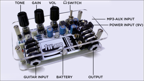
The folks at [ElectroSmash] recently released 1Wamp – a one watt, open hardware, Guitar amplifier packed with features. It consists of a JFET based pre-amplifier, a Big Muff Pi a.k.a BMP based Tone control and an LM386 power amplifier. The dual JFET pre-amp provides tube-like sound, the BMP provides a nice tonal range while the LM386 can drive various types of output’s ranging from headphones to speaker cabinets.

1Wamp had controls for Tone, Volume and Gain, a Speaker/Cabinet output, a headphone output with an integrated attenuator switch and an aux. input. The aux. input is handy as it adds any line level input signal to the guitar sound, allowing you to practice with metronome or MP3 backing tracks or drum bases. It runs off either a 9V battery or can be powered via an external power source. [ElectroSmash] have released all the native KiCad design files. If you’d like a quick look at the design, check out the Schematic PDF and the Bill of Materials. There’s also a handy assembly manual [PDF] that shows how to build it in five easy steps.

Their blog post provides extremely detailed circuit analysis of every part of the design, starting from the power supply filter to remove mains “hum” all the way through to PCB layout considerations for noise reduction. Oscilloscope screen shots provide signal analysis showing bias points and signal levels throughout the circuit. The choice of value for every component is explained, along with the consequences of changing those values. This makes it easy to customise the 1Wamp to suit individual tastes. We also noticed SPICE models for the recommended and alternative JFET transistors, in case you need to customise the design by changing component values.

There’s also a lot of audio amplifier trivia, references and links shared in their post. This includes a detailed analysis of the LM386 op-amp. Want to add some bling to your 1Wamp build? There are a lot of handy tips on how to add cool LED lighting to the amplifier if it is mounted in a standard metal enclosure. However, the PCB has some really nice graphics, so an acrylic-sandwich-type enclosures look best. Check out the video that walks through the features of the 1Wamp and shows off its performance. And while on the subject of Audio electronics, here’s one of their earlier projects – an open source Arduino guitar pedal.

Documentation to this level proves several things, most notably a love for this design and deep consideration for those who will use and modify this amplifier. It’s a great pattern to follow with your own Open Source designs.

Continue reading “1Wamp, An Open Hardware Guitar Amplifier”

Simple One-Chip Regenerative Receiver

Crystal radios may be the simplest kind to make, but regenerative receivers are more practical and only a little more complicated. A recent design by [Selenium] is super simple because it uses a single LM386 audio amplifier IC.

You might be surprised that you can convert an audio amplifier to a receiver using just a handful of components (a variable capacitor, a coil, a handful of capacitors, and a speaker). However, [Selenium] realized he could subvert the gain and bypass pins to cause regeneration and wound up with a very simple receiver.

If you haven’t looked at regenerative receivers before, the principle is simple (and dates back to 1912). An oscillator is an amplifier that gets (theoretically) an infinite amount of gain at one particular frequency. A regenerative receiver is just an amplifier that is almost (but not quite) at the point of oscillation. This gives it very high frequency-specific gain and a measure of selectivity. You can also nudge the receiver just into oscillation to receive CW or SSB signals.

[Selenium] built his prototype on an old receiver chassis because it had the IC and the variable capacitor already in place. However, others have built successful copies on breadboards ([Austin Heller] created several good looking breadboard versions) and on PCB material. [Selenium] also released some other unique LM386-based designs that use more parts (and, probably, have better performance). Looks like a simple way to build a practical receiver.