Mergers And Acquisitions: Analog Devices Snaps Up Maxim Integrated For $21 B

Analog Devices will acquire Maxim Integrated for $20.9 billion dollars in stock, as reported by Bloomberg this morning.

Perhaps the confusing part of the news is that the Bloomberg article mentions the acquisition will let Analog Devices better compete with Texas Instruments. Wait, didn’t Texas Instruments acquire Maxim back in 2015? Actually, no. There were rumors (reported then by Bloomberg) that TI was nearing an acquisition deal but it fell through in January of 2016.

You may remember that Analog Devices snapped up Linear Tech in a $30 B acquisition back in 2017. Considering this morning’s news, how will they compare to the might of TI? Looks like 2019 revenue for TI was $14.38 B while Analog reported $5.99 B. Add in Maxim’s revenue of $3.1 B and there’s still a David and Goliath scenario here. Although revenue doesn’t tell the whole story and the proverbial slingshot for Analog may be its existing portfolio of high-margin devices, grown even larger with this acquisition.

Considering how the last half decade played out, this might mark the beginning of another wild cycle of mergers and acquisitions. The consolidation trend continues as we approach a world where just a few gigantic semiconductor companies turn production lines up to eleven to fill the world’s insatiable appetite for more powerful electronics (and more electronics in general).

Ask Hackaday: How Does This Air Particle Sensor Work?

The hardware coming out of [Dr. Peter Jansen]’s lab is the craziest stuff you can imagine. He’s built a CT scanner out of plywood, and an MRI machine out of many, many turns of enamel wire. Perhaps his best-known build is his Tricorder – a real, all-sensing device with permission from the estate of [Gene Roddenberry] to use the name. [Peter]’s tricorder was one of the finalists for the first Hackaday Prize, but that doesn’t mean he’s stopped working on it. Sensors are always getting better, and by sometime in the 23rd century, he’ll be able to fit a neutrino detector inside a tiny hand-held device.

One of the new sensors [Peter] is working with is the MAX30105 air particle sensor. The marketing materials for this chip say it’s designed for smoke detectors and fire alarms, but this is really one of the smallest dust and particle sensors on the market. If you want a handheld device that detects dust, this should be the chip you’re looking at.

Unfortunately, Maxim is being very, very tight-lipped about how this particle sensor works. There is a way to get access to raw particle counts and the underlying algorithms, and Maxim is more than willing to sell those algorithms through a third-party distributor. That’s simply not how we do things around here, so [Peter] is looking for someone with a fancy particle sensor to collect a few hours of data so he can build a driver for this chip.

Here’s what we know about the MAX30105 air particle sensor. There are three LEDs inside this chip (red, IR, and green), and an optical sensor underneath a piece of glass. The chip drives the LEDs, light reflects off smoke particles, and enters the optical sensor. From there, magic algorithms turn this into a number corresponding to a particle count. [Peter]’s hackaday.io log for this project has tons of data, math, and statistics on the data that comes out of this sensor. He’s also built a test rig to compare this sensor with other particle sensors (the DSM501A and Sharp sensors). The data from the Maxim sensor looks good, but it’s not good enough for a Tricorder. This is where you, o reader of Hackaday, come in.

[Peter] is looking for someone with access to a fancy particle sensor to collect a few hours worth of data with this Maxim sensor in a test rig. Once that’s done, a few statistical tests should be enough to verify the work done so far and build a driver for this sensor. Then, [Peter] will be able to play around with this sensor and hopefully make a very cheap but very accurate air particle sensor that should be hanging on the wall of your shop.

Well Engineered Radio Clock Aces Form And Function

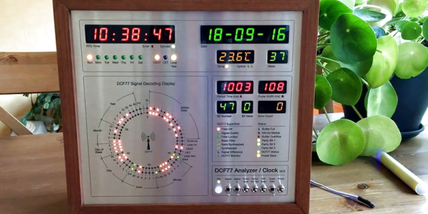
Clocks that read time via received radio signals have several advantages over their Internet-connected, NTP-synchronised brethren. The radio signal is ubiquitous and available over a fairly large footprint extending to thousands of kilometres from the transmitting antennae. This allows such clocks to work reliably in areas where there is no Internet service. And compared to GPS clocks, their front-end electronics and antenna requirements are much simpler. [Erik de Ruiter]’s DCF77 Analyzer/Clock is synchronised to the German DCF77 radio signal, which is derived from the atomic clocks at PTB headquarters. It features a ton of bells and whistles, while still being simple to build. It’s a slick piece of German hacker engineering that leaves us amazed.

Among the clock functions, it shows time, day of the week, date, CET/CEST modes, leap year indications and week numbers. The last is not part of the DCF77 protocol but is calculated via software. The DCF77 analyzer part has all of the useful information gleaned from the radio signals. There are displays for time period, pulse width, a bit counter, bit value indicator (0/1) and an error counter. There are two rings of 59 LEDs each that provide additional information about the DCF77 signal. A PIR sensor on the front panel helps put the clock in power save mode. Finally, there is a whole bunch of indicator LEDs and a bank of switches to control the various functions. On the rear panel, there are RJ45 sockets for the DCF77 receiver antenna board, temperature sensor and FTDI serial, a bunch of audio sound board controls, reset switches and a mode control switch.

His build starts with the design and layout of the enclosure. The front panel layout had to go through a couple of iterations before he was satisfied with the result. The final version was made from aluminium-coated sandwich-panel. He used an online service to photo-etch the markings, and then a milling machine to carve out the various windows and mounting holes. The rear panel is a tinted acrylic with laser engraving, which makes the neatly laid out innards visible for viewers to appreciate. The wooden frame is made from 40-year-old Mahogany, sourced from an old family heirloom desk. All of this hard work results in a really professional looking product.

The electronics are mostly off the shelf modules, except for the custom built LED driver boards. The heart of the device is an Arduino Mega because of the large number of outputs it provides. There are seven LED driver boards based around the Maxim 7221 (PDF) serial interface LED drivers – two to drive the inner and outer ring LEDs, and the others for the various seven-segment displays. The numerous annunciator LEDs are driven directly from the Arduino Mega. His build really comes together by incorporating a noise resilient DCF77 decoder library by [Udo Klein] which is running on a separate Arduino Uno. All of his design source files are posted on his GitHub repository and he hopes to publish an Instructable soon for those who would like to build one of their own.

In the first video below, he walks through the various functions of the clock, and in the second one, gives us a peek in to its inside. Watch, and be amazed.

Thanks for the tip, [Nick]

Continue reading “Well Engineered Radio Clock Aces Form And Function”

Decapsulation Reveals Fake Chips

A while back, [heypete] needed to get a GPS timing receiver talking to a Raspberry Pi. The receiver only spoke RS-232, and the Pi is TTL level serial. [Pete] picked up a few RS-232 to TTL conversion boards from an online vendor in China. These boards were supposedly based on the Max3232, a wonderchip that converts the TTL serial to the positive and negative voltages of RS-232 serial. The converters worked fine for a few weeks, before failing, passing a bunch of current, and overheating.

On Mouser and Digikey, the Max3232 costs about $1.80 in quantity one, and shipping is extra. You can pick up a ‘Max3232 converter board’ from the usual online marketplaces for seventy five cents with free shipping. Of course the Chinese version is fake. [Pete] had some nitric acid, and decided to compare the die of the real and fake Max3232s.

After desoldering two fake chips from their respective converter boards, and acquiring a legitimate chip straight from Maxim, [Pete] took a look at the chips under the microscope. The laser markings on the fakes are inconsistent, but there was something interesting to be found in the date code markings. It took two to four weeks for the fake chips to be etched with a date code, assembled into a converter board, shipped across the planet, put into [Pete]’s project, run for a little bit, and fail spectacularly. That’s an astonishing display of manufacturing, logistics, and shipping times. Update: The date codes on the fakes had 2013 laser etched on the plastic package, and 2009 on the die. The real chips had a date code just a few weeks before [Pete] decapped them — a remarkably short life but they gave in to a good cause.

Following the Zeptobars and CCC (PDF) guides to dropping acid, [Pete] turned his problem into solution and took a look at the dies under a microscope. The legitimate die was significantly larger, and the fake dies were identical. The official die used gold bond wires, but the fake ones didn’t.

Unfortunately, [Pete] isn’t an expert in VLSI, chip design, failure analysis, or making semiconductors out of sand. Anything that should be obvious to the layman is not, and [Pete] has no idea why these chips would work for a week, then overheat and fail. If anyone has an idea, hit [Pete] up and drop a note in the comments.

Mergers And Acquisitions: TI Looks To Snatch Up Maxim

BloombergBusiness is reporting rumors that Texas Instruments is in talks to acquire Maxim Integrated. Both companies have declined to respond to this leaked information. Earlier this year there were rumors that the two companies had been in talks in 2014 that didn’t result with an agreement.

We find it interesting that the article mentions Maxim doesn’t need to scale — yet we often find Maxim parts in short supply. If TI were to acquire the company this could change for some Maxium parts. Still, this move looks a lot like TI trying to bolster its hold on the portions of the analog chip market which both companies currently occupy.

Already this year we’ve seen Dialog acquire Atmel, Avago acquire Broadcom, and the merger agreement between Freescale and NXP. We probably missed a few, and this has us wonder who is next. Let us know what you think in the comments below.

[Thanks Kumar]

Maxim App Note Reuses Lithium Ion Cells — Plus Extras

Now we don’t sit around reading application notes for fun. But if hard pressed we would have to admit that we do read quite a few of them even if the concepts aren’t currently on our project list. That’s because they’re a great way to learn stuff and for the most part the information within is trustworthy.

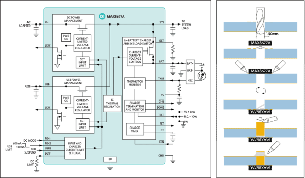
The latest one that we looked at is this Maxim app note 5681 on recycling Lithium-ion batteries. It’s more a reuse than a recycle but you get the point. If you have some Lithium-Ion cells left over from older equipment this resource delivers a lot of good information on how to use them to power something else.

Obviously they’re showing off their own hardware here, but that’s okay. The MAX8677A chips has a ton of features and can be had for $3-5 depending on your vendor. It automatically switches between powering your device from the battery, or from the charging source if connected. This allows you to source up to 500mA when connected to USB or 2A when charging from an external DC supply. There is also all of the protection you would normally want with a Li-ion setup, including temperature monitoring.

The catch is the not-so-hand-solderable QFN package. They’ve got a solution to this as well. The diagram on the right shows how to hand solder the chip — albeit with a hot air pencil — by drilling through the board to get at the ground pad from the underside of the PCB.

[Thanks Jaded and Amos]

How To Design Your Own LED Driver

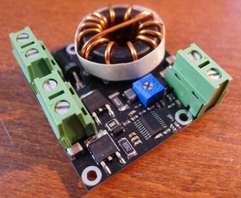
If you find yourself in need of a driver for a high power string of LEDs this is a must read. [Limpkin] just designed this driver as a contract job. He can’t show us the schematic, but he did share some tips on how to build an LED driver around a MAX16834 chip.

As you move to higher power designs the barriers to success pile up rather quickly. Using a chip like the MAX16834 really helps to simplify the task as it can be used as a boost or buck converter, it includes functionality that allows for dimming, and it’s a constant currents solution. There are board design issues that need to be accounted for in these designs. [Limkin] included links to a few calculators that will help you determine trace width based power levels used with the driver. He also recommends using copper pours on both sides of the board connected with vias to help dissipate heat. To that end he used an IR thermometer for feedback during testing.

It’s too bad he doesn’t have any photos of the device at work. If you build something similar please take some pictures and tip us off about it.