Battery Backup For RasPi Keeps Your Data Safe

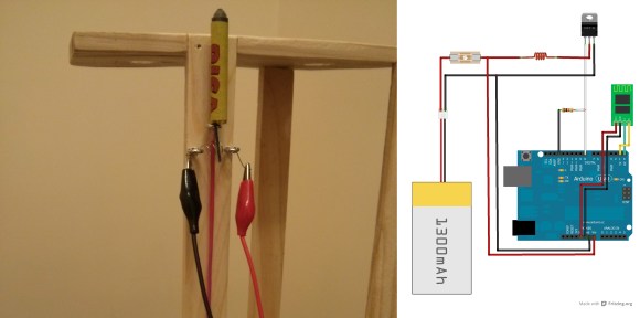
We’ve all raised a clench fist in anger over lost data, and it’s usually the result of unjustified optimism and lack of planning. [George] shared his solution that prepares for the worst: a circuit that provides backup power to a RasPi and its hard drives. [George’s] Pi setup runs as both an Apple Time Machine server and a website backup server, and a power outage could corrupt the data stored on the Pi’s attached hard drives.

Rather than turn to commercial solutions, however, [George] wanted to take advantage of the Pi’s low power consumption and create an inexpensive custom circuit that would safely and automatically power down the devices upon loss of power. To detect a power failure, the build connects one of the Pi’s GPIOs to an opto-isolator, which—through a zener diode—connects to the 12V wall adapter: though [George] welcomes suggestions for alternative methods of safely identifying a mains power loss. The rest of the circuit serves as a trickle charger for the two attached 9V batteries and as a regulator to supply the correct voltage to the RasPi. Power MOSFETs connected to a GPIO handle the delayed power off.

You can view (and edit!) the circuit online here and find the relevant source code on [George’s] website. If you want to build your own RasPi file server, try cramming all the parts into an old optical drive enclosure.

Bluetooth Audio Adapter Hacked To Switch Off Amplified Speakers

bluetooth-audio-amp-auto-switch

This Bluetooth Audio Adapter is meant to connect a Bluetooth audio source (like a smartphone or tablet) to a speaker system with a plain old line-in connection. It has the ability to automatically connection when the Bluetooth device comes into range. Sounds convenient until [Andreas Pösch] points out that he still has to switch the speakers on and off manually. This hack automates the entire thing using a bit of additional hardware.

If you look closely you’ll see that the black cables have barrel jacks. This is a power pass-through rig that he whipped up. The protoboard includes a 7805 linear regulator which feeds power to the green circuit board in lieu of it’s original power adapter. A MOSFET switches outbound power headed for the speakers. All of it fits inside of the original enclosure, and he only had to add one port for the AC adapter.

This would be absolutely perfect for an antique radio retrofit. One of these adapters can be had for just over thirty bucks!

Building A DC Constant Current/Power Electric Load

By just looking at the picture above, we’re pretty sure that most Hackaday readers will have guessed by now that much power can be dissipated by this electric load. For those who don’t know, an electric load (or dummy load) is a device used to simulate a load on a system for testing purposes. This is quite handy when measuring battery capacities or testing power supplies.

The heart of the device that [Kerry] designed is based on 6 power MOSFETs, a few operational amplifiers and an Arduino compatible ATmega328p microcontroller. Sense resistors are used to measure how much current is passing through the MOSFETs (and therefore the load), the MCP4921 Digital to Analog Converter (DAC) from microchip is used to set the current command, and the load’s voltage is measured by the ATmega ADC. Measuring the latter allows a constant power load mode (as power = current * voltage). In his article, [Kerry] shows that he can simulate a load of up to 200W.

Continue reading “Building A DC Constant Current/Power Electric Load”

Making A Power Inductor Checker

inductor-checker-for-oscilloscope

Back to the basics: there are three kinds of passive electronic components: Inductors, Capacitors and Resistors. An inductor can be easily built and many types of core and bobbin kits are available. However, characterizing one hypothetical coil you just made is quite tricky as its inductance will depend on the measurement frequency and DC bias current. That’s why [ChaN] designed the circuit shown above.

As you may guess, RF enthusiasts are more interested in the inductance vs frequency curve while power circuit designers prefer inductance vs load current (for a given frequency). The basic principle behind the circuit shown above is to load an inductor for repetitive short periods and visualizing the current curve with an oscilloscope connected to a sense resistor. When loading the inductor, the current curve will be composed of two consecutive slopes as at a given moment the coil’s core will be saturated. Measuring the slope coefficient then allows us to compute the corresponding inductance.

[Via Dangerous Prototypes]

Fail Of The Week: Flaming Brushless Motor Controller

Yep, smoke and flames are usually a sign that your electronics aren’t functioning as expected. This is actually the second failure encountered while learning about brushless motor controllers.

[Michael Kohn] purchase the motor while working on a different project and it went unused for quite some time. When he came across it again he decided he should learn the not-so-dark art of BLDC control.

The first hurdle was to figure out how to drive the three-wire motor when he had been expecting only two. The answer required him to come up with switching mechanism that allows three states for each wire: positive, negative, and not connected. His solution was to use MOSFETs. It’s a good idea, but unfortunately during the first iteration they were under-spec’d and he scared the crap out of himself when one of them blew up during testing (clip #1 below). After sourcing a more robust set of MOSFETs [Micheal] went back to testing which is when this little fire broke out. The 22 gauge wires connecting the Lithium battery to the driver just couldn’t cut it. See for yourself in the second clip.

It’s been awhile since we’ve said it: Please remember the Fail of the Week is not about ridiculing the hacker who was gracious enough to document his or her failure. It’s about learning from the mistake and discussing alternatives that can help others in the future. For instance, in this case some advice in determining MOSFET specs and wire gauge for any type of motor would be quite helpful. Have at it in the comments.

Continue reading “Fail Of The Week: Flaming Brushless Motor Controller”

Interactive Boozeshelf Is Its Own Dance Party

boozeshelf

[Jeremy] refused to settle on your typical alcohol storage options, and instead created the Boozeshelf. Like most furniture hacks, the Boozeshelf began as a basic IKEA product, which [Jeremy] modified by cutting strips of wood to serve as wine glass holders and affixing the front end of a wine rack at the base to store bottles.

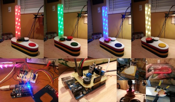
In its standard operating mode the Boozeshelf lies dark and dormant. Approaching it triggers a cleverly recessed ultrasonic sensor that gently illuminates some LEDs, revealing the shelf’s contents. When you walk away, then lights fade out. An Arduino Mega running [Jeremy’s] custom LEDFader library drives the RGB LED strips, which he wired with some power MOSFETS to handle current demands.

[Jeremy] didn’t stop there, however, adding an additional IR receiver that allows him to select from three different RGB LED color modes: simple crossfading, individual shelf colors (saved to the on-board EEPROM), or the festive favorite: “Dance Party Mode.” Stick around after the break to see [Jeremy] in full aficionado attire demonstrating his Boozeshelf in a couple of videos. Considering blackouts are a likely result of enjoying this hack, we recommend these LED ice cubes for your safety.

Continue reading “Interactive Boozeshelf Is Its Own Dance Party”

The Easy Or Hard Way To Build A PWM Dimmer

From what you would gather from Hackaday’s immense library of builds and projects over several years, the only way to do PWM is with a microcontroller, some code, a full-blown IDE, or even a real-time operating system. To some readers, we’re sure, this comes naturally and with an awesome toolchain it can be as easy as screwing in a light bulb. There is, of course, an easier way.

[Jestin] needed to vary the current on a small 12 Volt load. Instead of digging out an in system programmer, he turned to the classic 555 chip. With a single pot, it’s easy to vary the duty cycle of the 555 and connect that to a MOSFET. Put a load in there, and you have a very easy circuit that’s a fully functioning PWM dimmer.

If all you have are a few scraps in your part drawers, this is a very, very easy way to set up a dimmer switch. We’re also loving [Jestin]’s improv aluminum tube enclosure, as seen in the video below.

Continue reading “The Easy Or Hard Way To Build A PWM Dimmer”