Metal detectors can be a great source of fun, and occasionally even found wealth. They allow the detection of metal objects at a distance, enabling hidden treasures to be discovered. They’re also highly critical to the work of minesweepers and unexploded ordnance disposal teams. [Andrius] wanted to add such a device to his kit when motorcycling through the woods of Lithuania, and thus decided to undertake a build of his own. (Editor’s note: original link went bad, this is through the Wayback Machine.)
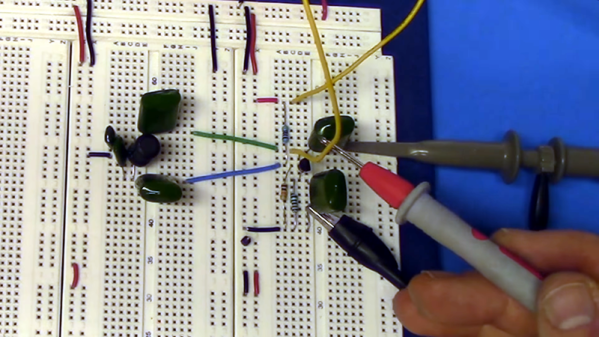
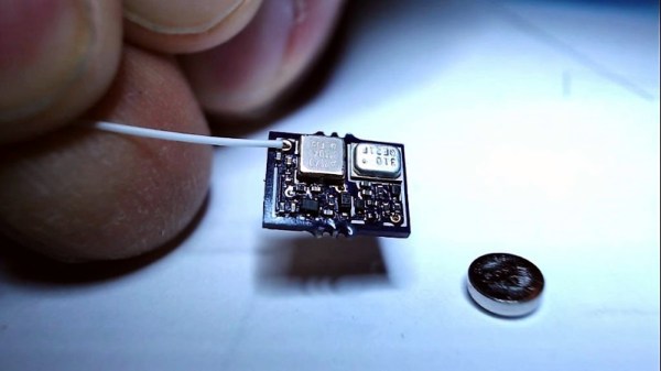
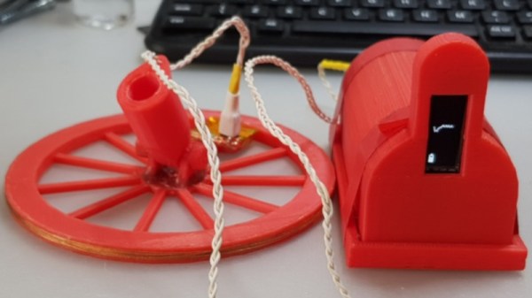
The detector is a thoroughly modern one – fans of the 555 may want to look away now. A Collpits oscillator, built from two transistors, is used to generate a frequency that is passed through the detection coil. This frequency is measured by an Arduino that plots a graph of the received frequency on an OLED display. As the coil is passed near metal objects, the oscillator frequency changes, and this is visible on the frequency plot on-screen.
Not only is it a quick and easy build that is achievable from what are now junkdraw components, it’s also one that would be readily usable by the hearing-impaired, too. It’s a great project to tackle if you’re looking to get to grips with basic oscillators, frequency measurement, or just microcontroller programming in general.
Still need more inspiration? We’ve seen a similar concept executed before.