PCB Metro Maps Are A Gorgeous Labor Of Love

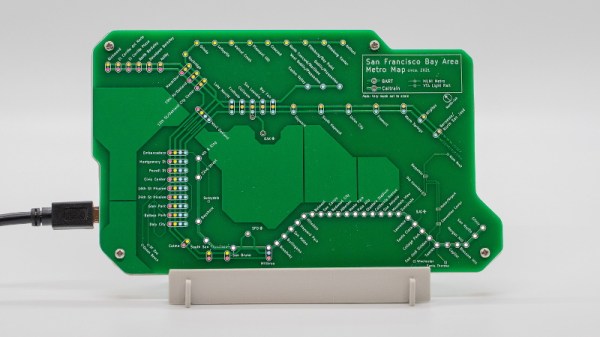
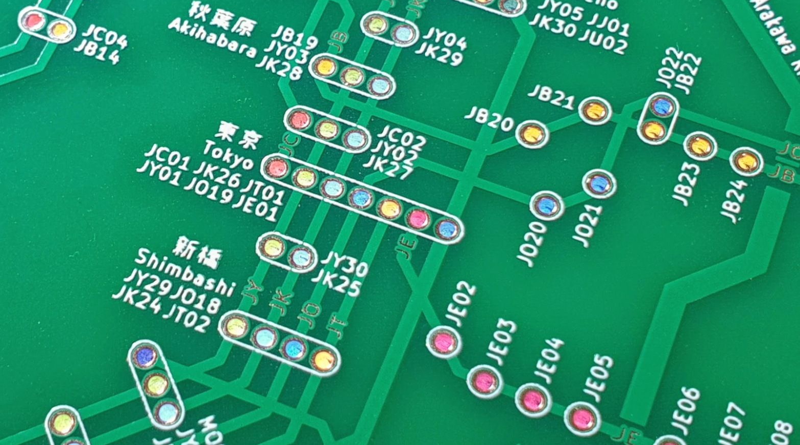
Is your love of public transportation matched only by your passion for designing custom PCBs? If so, then you’re going to love these phenomenal transit maps created by [Chai Jia Xun]. Using the painstakingly refined principles outlined in his detailed write-up, he’s created versions for Tokyo, Singapore, and the comparatively spartan San Francisco Bay Area. All you need to make one up for your home town is an incredible amount of patience and dedication. No problem, right?

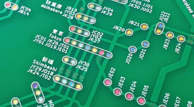
As [Xun] explains, the first part of creating one of these maps isn’t unlike generating a normal PCB. Just make a footprint for the stations, consult with Google Maps as to where they should be placed on the board, and then connect them all up with traces to stand in for the rail lines. A little silkscreen work, and you’re done.

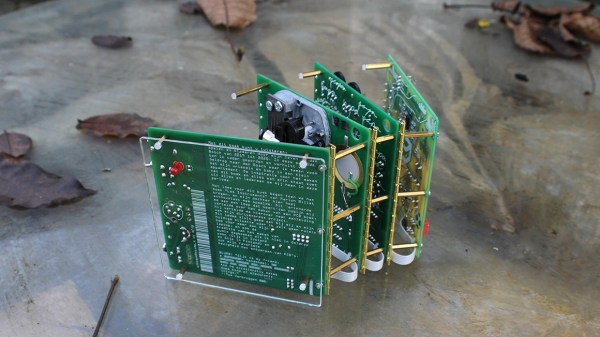
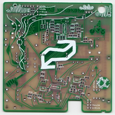
Well…unless you want them to light up, anyway. To pull that off, [Xun] created a second PCB that places an LED behind each station hole drilled in the previous board. With a microcontroller and shift register, he’s able to selectively illuminate individual lines and run through different patterns. To combat light bleeding through the PCB, a CNC-cut piece of 3 mm MDF sits between the two boards to make sure each LED is only visible through the respective hole in the top surface.

You could call the map finished here as well, assuming you don’t mind all the stations lighting up white. If you want them to be different colors, you’ll need to insert some colored diffusers. [Xun] went through several different approaches here, but in the end, the idea that seemed to work best was to simply print out all the colored dots on a piece of transparency paper and use a second sheet of tracing paper to soften the light. Alignment here is critical, but once everything is dialed in, the results are quite impressive.

It’s quite a bit of work, and we haven’t even mentioned the fact that [Xun] had to modify the circuit when it came time to do the Tokyo map, as some MOSFETs had to be added into the mix for the microcontroller to reliably control 350+ LEDs. So there’s certainly no shame in simply buying one of them when they go on sale instead of trying to recreate it from scratch. Assuming you live in one of the cities he’s offering, anyway. Otherwise, you might want to take a look at our HackadayU class on KiCad and get yourself a comfortable chair.

Hiding Behind The Silkscreen: The Carolinacon 2021 Badge Has A Secret

The pandemic may have taken away many of our real-world events, but as they’ve gone online their badge teams have often carried on regardless. One of these comes from Carolinacon, and it’s decided to eschew the bleeding edge of electronic wizardry and instead push slightly at the boundaries of PCB art. It contains a hidden message in a copper layer behind a band of white silkscreen, which is revealed by a set of LEDs on the reverse of the board shining through the translucent FR4.

Electronics-wise it’s a pretty simple design, sporting only an ATtiny microcontroller and a photoresistor alongside the LEDs, and with the secret message being triggered when the badge is placed in the dark. The conference’s pig logo is eye-catching, but it has no pretences towards being a dev board or similar. The technique of LEDs behind copper and silkscreen is an interesting one though, and something that we think could bear more investigation in future designs. It’s pleasing to see that there are still new avenues to be taken in the world of PCB-based art.

This isn’t the first time this event has had an eye-catching badge, we’ve covered one of their previous offerings.

A PCB Diary

[Gijs Gieskes] has made another eye-catching PCB wonder, this time a diary built from several circuit boards which are assembled into a book, not unlike a PC/104 system. But with [Gijs]’s system you can easily open the stack-up to access single boards without disassembling the whole thing. We don’t see brass piano hinges on PCB assemblies very often, but [Gijs]’s PCB designs are anything but conventional. Hint: if you wanted to recreate this technique using more ordinary hardware, you can find hinged PCB standoffs from various suppliers.

Bicycle, soccer ball, smoke on the “No no no no no…” PCB

Apparently it’s more than a passive piece of art.  Each board has several circuits, some of which (all?) are functioning is ways not clearly described, which seems to be intentional. According to his build log, different things happen when you mix and match the inter-board ribbon cables in various ways. We are told in the instructions “to just try and see what happens”. No schematics are posted, but there is a partial description of the circuits in the manual and parts on the two-layer boards are well-labeled. Although after spot checking a few circuits board photos, we’d guess that no small number of traces, and perhaps some parts, are wild goose chases.

The project claims to be a diary for the years 2018 and 2019, but we will leave it as an exercise for the reader to interpret the messages that [Gijs] has embedded into this fascinating piece. We have written about several of his projects over the years, such as this crazy bent Casio SK-1 from all the way back in 2005. And before dismissing this “book” style of circuit board stack-up as only for artists, check out this teardown of a Soyuz clock we covered back in January.

When Only The Tiniest Of Violins Will Do

Playing the tiniest of violins may be a phrase to encapsulate the complete lack of sympathy as someone unpleasant receives their just deserts, but have any of you ever considered how such a feat might be achieved? Unless you’re an unusually talented virtuoso with the bow, it’s difficult to believe that such a small instrument could be played with ease, even if it were to be available in the first place.

Happily a solution is at hand to all those minuscule stringed instrument woes, courtesy of [Alexandra Covor], who has created a miniature PCB violin that is after a fashion playable. It may not be a conventional instrument with a horsehair bow and traditional sounding mechanism, but its electronic voice should still deliver enough to delight.

At the heart of the violin-shaped PCB is an ATtiny85 and a piezoelectric buzzer, and just where you might expect them are a set of strings made from wire attached to the PCB. The instrument can play stored tunes, but since the strings are hooked up to an analogue input on the microcontroller, it can be played as a touch instrument. Finally a pair of LEDs behind the translucent FR4-only F-holes complete the look. It’s fair to say that Itzhak Perlman and his ilk are safe from challengers bearing this instrument, but it’s still an eye-catching piece of PCB art.

This isn’t the first tiny violin that’s been featured here, some others are much smaller.

Classical Poultry Conditioning Is A Bird-Brained Scheme

A while back, [Kutluhan Aktar] was trying to hack their chickens, quails, and ducks for higher egg production and faster hatching times by using a bit of classical conditioning. That is, feeding them at the same time every day while simultaneously exposing them to sound and light. Once [Kutluhan] slipped enough times, they hatched a plan to build an automatic feeder.

This fun rooster-shaped bird feeder runs on an Arduino Nano and gets its time, date, and temperature info from a DS3231 RTC. All [Kutluhan] has to do is set the daily feeding time. When it comes, a pair of servos and a pan-tilt kit work together to invert a Pringles can filled with food pellets. A piezo buzzer and a green LED provide the sound and light to help with conditioning. Scratch your way past the break to see it in action.

If [Kutluhan] gets tired of watching the birds eat at the same time every day, perhaps a trash-for-treats training program could be next on the list.

Continue reading “Classical Poultry Conditioning Is A Bird-Brained Scheme”

Modular Vibrating ‘Bots Made From PCBs

Printed circuit boards, they’re a medium designed primarily to mount electrical components with the wires themselves places as copper traces on the boards. To accommodate wide range of needs that have arisen over decades, board houses have evolved all manner of advanced techniques in routing and plating. To our benefit, this also makes it possible to leverage PCBs in an entirely artistic way, taking advantage of the highly-optimized manufacturing process. [GeeekClub] did just that, creating awesome vibrating robots out of custom-made PCBs.

The ‘bots come as a single PCB, with the parts snapped out akin to removing parts from sprues in a plastic model kit. They can then be assembled, with a pair of pager vibration motors installed to provide motive power. But really it’s the aesthetic of the boards and not the functionality that make these so incredible.

The design nestles a coin cell in the base of each bot, providing power and using the weight to help keep them upright. There’s a smattering of LEDs on board, and the art style of the ‘bots draws from Hopi Indian, Asian, and South American influences.

Cyphercon 2017 featured these exciting cubic badges, created from PCBs and soldered by hand.
This Star Trek inspired piece shows just how far you can go with the right color soldermask and some creativity.

This “flat-pack” style of PCB design that comes to life with creative use of angles and layers is becoming its own sub-genre of the art. The Star Trek Enterprise inspired build in another great example. We’ve also seen a growing trend of using the PCB as enclosures, take the Cyphercon badge and Queercon badge projects from 2017 as examples. Get yourself up to speed on design techniques for using FR4 as an enclosure from [Voja Antonic’s] in-depth guide.

Bringing Back The Fidget Toy Craze With The Magic Microcontroller Cube

[Rickysisodia] had a few dead ATmega128 chips laying around that he didn’t want to just throw away, so he decided to turn them into his own light-up fidget toy. The toy is in the form of a six-sided die so small that you can hang it on a keychain. He soldered an ATmega128 on each side of the cube and added a few dot circles to give his toy the look of a functional dice. We were pretty amazed by his impressive level of dexterity. Soldering those 0.8 mm-pitch leads together seems pretty tedious if you ask us.

Then he wired a simple, battery-powered tilt switch LED circuit on perfboard that he was able to sneakily place inside the cube. He used a mercury switch, which, as you may figure, uses a small amount of mercury to short two metal contacts inside the switch, completing the circuit and lighting the LED. We would suggest going with the non-mercury variety of tilt switches just to avoid any possible contamination. You know us, anything to mitigate unnecessary disasters is kind of a good route. But anyway, the die lights up a different color LED based on the orientation of the cube and it even blinks.

This is a pretty cool hack for wowing your friends at your next PCB art meet-up. We’ll probably put this in the electronics art category, so it doesn’t get lumped in with those other ever-beloved fidget toys.

Continue reading “Bringing Back The Fidget Toy Craze With The Magic Microcontroller Cube”