What Else Is An M.2 WiFi Slot Good For?

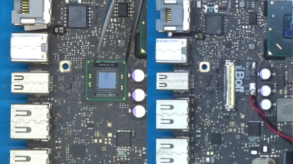
Many mainboards and laptops these days come with a range of M.2 slots, with only a subset capable of NVME SSDs, and often a stubby one keyed for ‘WiFi’ cards. Or that’s what those are generally intended to be used for, but as [Peter Brockie] found out when pilfering sites like AliExpress, is that you can get a lot of alternate expansion cards for those slots that have nothing to do with WiFi.

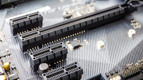
Why this should be no surprise to anyone who knows about the M.2 interface is because each ‘key’ type specifies one or more electrical interfaces that are available on that particular M.2 slot. For slots intended to be used with NVME SSDs, you see M-keying, that makes 4 lanes of PCIe available. The so-called ‘WiFi slots’ on many mainboards are keyed usually for A/E, which means two lanes of PCIe, USB 2.0, I2C and a few other, rather low-level interfaces. What this means is that you can hook up any PCIe or or USB (2.0) peripheral to these slots, as long as the bandwidth is sufficient.

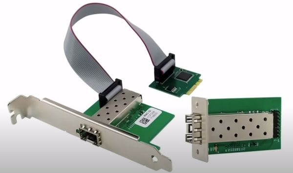
What [Peter] found includes adapter cards that add Ethernet (1 Gb, 2.5 Gb), USB 2.0 ports, SIM card (wireless adapter?), an SFP fiber-based networking adapter, multiple M.2 to 2+ SATA port adapters, tensor accelerator chips (NPUs) and even a full-blown M.2 to x16 PCIe slot adapter. The nice thing about this is that if you do not care about using WiFi with a system, but you do have one of those ports lounging about uselessly, you could put it to work for Ethernet, SFP, SATA or other purposes, or just for hooking up internal USB devices.

Clearly this isn’t a market that has gone unexploited for very long, with a bright outlook for one’s self-designed M.2 cards. Who doesn’t want an FPGA device snuggled in a PCIe x2 slot to tinker with?

Continue reading “What Else Is An M.2 WiFi Slot Good For?”

On the left, the Thunderbolt chip as mounted on the motherboard originally. On the right, the shim installed in place of a Thunderbolt BGA chip, with the IPEX connector soldered on

Macbook Gets NVMe SSD With Help Of A BGA-Imitating PCB

Recently, we stumbled upon a video by [iBoff], adding an M.2 NVMe port to a 2011-2013 MacBook. Apple laptops never came with proper M.2 ports, especially the A1278 – so what’s up? The trick is – desoldering a PCIe-connected Thunderbolt controller, then soldering a BGA-like interposer PCB in place of where the chip was, and pulling a cable assembly from there to the drive bay, where a custom adapter PCB awaits. That adapter even lets you expose the PCIe link as a full-sized PCIe 4x slot, in case you want to connect an external GPU instead of the NVMe SSD!

The process is well-documented in the video, serving as an instruction manual for anyone attempting to install this specific mod, but also a collection of insights and ideas for anyone interested in imitating it. The interposer board ships with solder balls reballed onto it, so that it can be installed in the same way that a BGA chip would be – but the cable assembly connector isn’t installed onto the interposer, since it has to be soldered onto the mainboard with hot air, which would then melt the connector. The PCB that replaces the optical drive makes no compromises, either, tapping into the SATA connector pins and letting you add an extra 2.5mm SATA SSD.

Adding an NVMe drive is an underappreciated way to speed up your old laptop, and since they’re all PCIe under the hood, you can really get creative with the specific way you add it. You aren’t even limited to substituting obscure parts like Thunderbolt controllers – given a laptop with a discrete GPU and a CPU-integrated one, you could get rid of the discrete GPU and replace it with an adapter for one, or maybe even two NVMe drives, and all you need is a PCB that has the same footprint as your GPU. Sadly, the PCB files for this adapter don’t seem to be open-source, but developing a replacement for your own needs would be best started from scratch, either way.

We’ve seen such an adapter made for a Raspberry Pi 4 before, solderable in place of a QFN USB 3.0 controller chip and exposing the PCIe signals onto the USB 3 connector pins. However, this one takes it up a notch! Typically, without such an adapter, we have to carefully solder a properly shielded cable if we want to get a PCIe link from a board that never intended to expose one. What’s up with PCIe and why is it cool? We’ve talked about that in depth!

Continue reading “Macbook Gets NVMe SSD With Help Of A BGA-Imitating PCB”

A Real GPU On The Raspberry Pi — Barely.

[Jeff Geerling] saw the Raspberry Pi Compute Module 4 and its exposed PCI-Express 1x connection, and just naturally wondered whether he could plug a GPU into that slot and get it to work. It didn’t. There were a few reasons why, such as the limited Base Address Register space, and drivers that just weren’t written for ARM hardware. A bit of help from the Raspberry Pi software engineers and other Linux kernel hackers and those issues were fixed, albeit with a big hurdle in the CPU. The Broadcom chip in the Pi 4, the BCM2711, has a broken PCIe implementation.

There has finally been a breakthrough — Thanks to the dedicated community that has sprung up around this topic, a set of kernel patches manage to work around the hardware issues. It’s now possible to run a Radeon HD 5000/6000/7000 card on the Raspberry Pi 4 Compute Module. There are still glitches, and the Kernel patches to make this work will likely never land upstream. That said, It’s possible to run a desktop environment on the Radeon GPU on a Pi, and even a few simple benchmarks. The results… aren’t particularly inspiring, but that wasn’t really ever the point. You may be asking what real-world use is for a full-size GPU on the Pi. Sure, maybe crypto-mining or emulation, or being able to run more monitors for digital signage. More than that, it might help ensure the next Pi has a working PCIe implementation. But like many things we cover here, the real reason is that it’s a challenge that a group of enthusiasts couldn’t leave alone.

Continue reading “A Real GPU On The Raspberry Pi — Barely.”

Picture of the setup described in the article, with PCI-E cards strewn around the desk, all interconnected, and a powered-up laptop, a large TV screen behind the laptop

This Laptop Gets All The PCIe Devices

Did you ever feel like your laptop’s GPU was sub-optimal, or perhaps that your laptop could use a SAS controller? [Rob Rogers] felt like that too, so now he has the only Dell Latitude business-class laptop that’s paired with an AMD RX580 GPU – and more. Made possible because of a PCIe link he hijacked from the WiFi card, he managed to get a SAS controller, a USB 3.0 expansion card, the aforementioned GPU and a dual-port server network adapter, all in a single, desk-top setup, as the video demonstrates.

First off, we see a PCIe packet switch board based on a PLX-made chip, wrapped in blue tape, splitting a single PCIe x1 link into eight. The traditional USB 3.0 cables carry the downstream x1 links to the four PCIe cards connected, all laid out on [Rob]’s desk. [Rob] demonstrates that all of the cards indeed function correctly – the SAS controller connected to a server backplane with whole 22 TB of storage in it, a few devices plugged into a USB 3.0 card, an Ethernet cable with an active link in the network card, and wrapping up the video showing 3DMark results of the RX580 clearly paired with the laptop’s mobile CPU. There’s four more spots on the PCIe switch card, so if you wanted to connect a few NVMe SSDs without the costly USB enclosures that usually entails, you absolutely could!

The setup on the desk, laptop-less, still interconnected and with the mini pci-e adapter visible
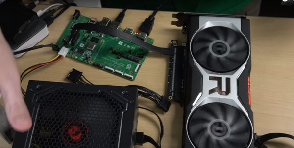
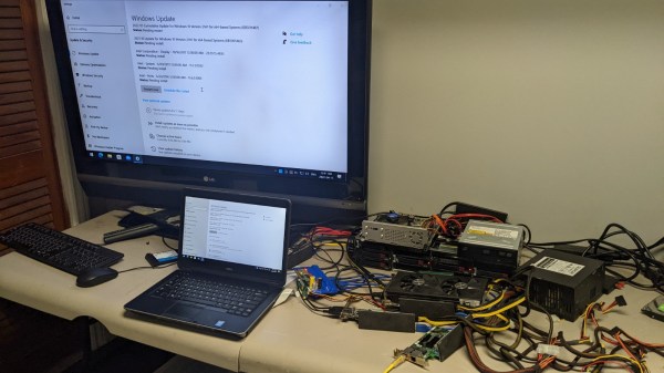
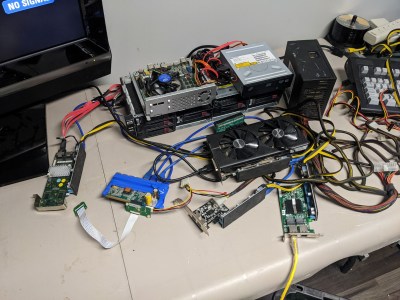
Now, there’s a reason why we don’t see more of such hacks. This seems to be a Latitude E5440 and the card is plugged into a mini-PCIe slot, which means the entire contraption is bound by a single PCI-E Gen2 x1 link, heavily offsetting the gains you’d get from an external GPU when, say, gaming. However, when it comes to the types and amount of peripherals, this is unbeatable – if you want to add an external GPU, high-speed networking and a SAS controller to the same computer that you usually lug around, there isn’t really a dock station you can buy for that!

Our collection of cool PCIe hacks has been growing, with hackers adding external GPUs through ExpressCard and mini PCIe alike, fitting PCIe slots where the factory refused to provide one, and extending the onboard M.2 slots for full-size PCIe cards. Nowadays, with these packet switches, it’s easy as ever to outfit any PCIe capable device with a whole slew of features – as this Raspberry Pi Computer Module motherboard with eleven PCIe slots demonstrates. Wonder how PCIe works, and why all of that is possible? We’ve written an entire article on that!

Continue reading “This Laptop Gets All The PCIe Devices”

The Bus That’s Not A Bus: The Joys Of Hacking PCI Express

PCI Express (PCIe) has been around since 2003, and in that time it has managed to become the primary data interconnect for not only expansion cards, but also high-speed external devices. What also makes PCIe interesting is that it replaces the widespread use of parallel buses with serial links. Instead of having a bus with a common medium (traces) to which multiple devices connect, PCIe uses a root complex that directly connects to PCIe end points.

This is similar to how Ethernet originally used a bus configuration, with a common backbone (coax cable), but modern Ethernet (starting in the 90s) moved to a point-to-point configuration, assisted by switches to allow for dynamic switching between which points (devices) are connected. PCIe also offers the ability to add switches which allows more than one PCIe end point (a device or part of a device) to share a PCIe link (called a ‘lane’).

This change from a parallel bus to serial links simplifies the topology a lot compared to ISA or PCI where communication time had to be shared with other PCI devices on the bus and only half-duplex operation was possible. The ability to bundle multiple lanes to provide less or more bandwidth to specific ports or devices has meant that there was no need for a specialized graphics card slot, using e.g. an x16 PCIe slot with 16 lanes. It does however mean we’re using serial links that run at many GHz and must be implemented as differential pairs to protect signal integrity.

This all may seem a bit beyond the means of the average hobbyist, but there are still ways to have fun with PCIe hacking even if they do not involve breadboarding 7400-logic chips and debugging with a 100 MHz budget oscilloscope, like with ISA buses.

Continue reading “The Bus That’s Not A Bus: The Joys Of Hacking PCI Express”

NVMe Blurs The Lines Between Memory And Storage

The history of storage devices is quite literally a race between the medium and the computing power as the bottleneck of preserving billions of ones and zeros stands in the way of computing nirvana. The most recent player is the Non-Volatile Memory Express (NVMe), something of a hybrid of what has come before.

The first generations of home computers used floppy disk and compact cassette-based storage, but gradually, larger and faster storage became important as personal computers grew in capabilities. By the 1990s hard drive-based storage had become commonplace, allowing many megabytes and ultimately gigabytes of data to be stored. This would drive up the need for a faster link between storage and the rest of the system, which up to that point had largely used the ATA interface in Programmed Input-Output (PIO) mode.

This led to the use of DMA-based transfers (UDMA interface, also called Ultra ATA and Parallel ATA), along with DMA-based SCSI interfaces over on the Apple and mostly server side of the computer fence. Ultimately Parallel ATA became Serial ATA (SATA) and Parallel SCSI became Serial Attached SCSI (SAS), with SATA being used primarily in laptops and desktop systems until the arrival of NVMe along with solid-state storage.

All of these interfaces were designed to keep up with the attached storage devices, yet NVMe is a bit of an odd duck considering the way it is integrated in the system. NVMe is also different for not being bound to a single interface or connector, which can be confusing. Who can keep M.2 and U.2 apart, let alone which protocol the interface speaks, be it SATA or NVMe?

Let’s take an in-depth look at the wonderful and wacky world of NVMe, shall we?

Continue reading “NVMe Blurs The Lines Between Memory And Storage”

Adding PCIe To Your Raspberry Pi 4, The Easier Way

Ever since people figured out that the Raspberry Pi 4 has a PCIe bus, the race was on to be the first to connect a regular PCIe expansion card to a Raspberry Pi 4 SBC. Now [Zak Kemble] has created a new approach, using a bridge PCB that replaces the VL805 USB 3 controller IC. This was also how the original modification by [Tomasz Mloduchowski] worked, only now it comes in a handy (OSHPark) PCB format.

After removing the VL805 QFN package and soldering in the bridge PCB, [Zak] confirmed that everything was hooked up properly and attempted to use the Raspberry Pi 4 with a PCIe extender. This showed that the Raspberry Pi would happily talk with a VL805-based USB 3.0 PCIe expansion card, as well as a Realtek RTL8111-based Ethernet card, but not a number of other PCIe cards. Exactly why this is is still unclear at this point.

As a bonus, [Zak] also found that despite the removal of the VL805 IC from the Raspberry Pi rendering its USB 3 ports useless, one can still use the USB-C ‘power input’ on the SBC as a host controller. This way one can have both PCIe x1 and USB on a Raspberry Pi 4.

This is the third iteration we’ve seen for using PCIe with the Pi. If you’re building on the work of [Thomasz Mloduchowski], which inspired [Colin Riley] to add expanders, and now this excellent hack by [Zak], we want to hear about it!

(Thanks to Itay for the tip)