After the Pi 4 released, a discovery was quickly made that the internals of the popular single-board computer use PCIe to communicate with each other. This wasn’t an accessible PCIe bus normally available in things like desktop computers for expansion cards, though; this seemed to be done entirely internally. But a few attempts were made to break out the PCIe capabilities and connect peripherals to it anyway, with varying levels of success. The new Pi 5 seems to have taken that idea to its logical conclusion and included a PCIe connector, and [George] is showing us a way to interface with this bus.
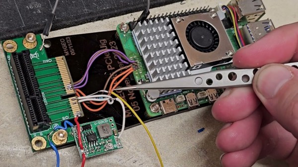
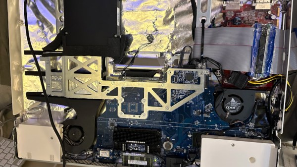
The bus requires the port to be enabled, but once that’s done it’s ready to be used. First, though, some support circuitry needs to be worked out which is why [George] is reverse engineering the system to see what’s going on under the hood. There are a few handshakes that happen before it will work with any peripherals, but with that out of the way a PCIe card can be connected. [George] removed the connector to solder wires to the board directly in order to connect a proper PCIe port allowing a variety of cards to be connected, in this case a wireless networking card and an old Firewire card. This specific build only allows Gen 1 speeds, but the bus itself supports faster connections in theory with better wiring and support circuitry.
While it might not be the prettiest solution, as [George] admits, it does a great job of showing the inner workings of this communication protocol and its use in the new, more powerful Raspberry Pi 5. This makes a lot of things more accessible, such as high-speed PCIe HATs allowing for a wide range of expansion for these popular single-board computers, which wouldn’t have been possible before. If you’re still stuck with a Pi 4, though, don’t despair. You can still access the PCIe bus on these older models but it’ll take a little bit more work.
Thanks to [CJay] for the tip!

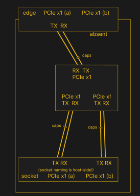 PCIe needs TX pairs connected to RX on another end, like UART – and this is non-negotiable. Connectors will use host-side naming, and vice-versa. As the diagram demonstrates, we connect the socket’s TX to chip’s RX and vice-versa; if we ever get confused, the laptop schematic is there to help us make things clear. To sum up, we only need to flip the names on the link coming to the PCIe switch, since the PCIe switch acts as a device on the card; the two links from the switch go to the E-key socket, and for that socket’s purposes, the PCIe switch acts as a host.
 You might have heard the term “bifurcation” if you’ve been around PCIe, especially in mining or PC tinkering communities. This is splitting a PCIe slot into multiple PCIe links, and as you can imagine, it’s quite tasty of a feature for hackers; you don’t need any extra hardware, really, all you need is to add a buffer for REFCLK. See, it’s still needed by every single extra port you get – but you can’t physically just pull the same clock diffpair to all the slots at once, since that will result in stubs and, consequently, signal reflections; a REFCLK buffer chip takes the clock from the host and produces a number of identical copies of the REFCLK signal that you then pull standalone. You might have seen x16 to four NVMe slot cards online – invariably, somewhere in the corner of the card, you can spot the REFCLK buffer chip. In a perfect scenario, this is all you need to get more PCIe out of your PCIe.


