With rescue and recovery efforts at the horrific condo collapse in Florida this week still underway, we noted with interest some of the technology being employed on the site. Chief among these was a contribution of the Israeli Defense Force (IDF), whose secretive Unit 9900 unveiled a 3D imaging system to help locate victims trapped in the rubble. The pictures look very much like the 3D “extrusions” that show up on Google Maps when you zoom into a satellite view and change the angle, but they were obviously built up from very recent aerial or satellite photos that show the damage to the building. The idea is to map where parts of the building — and unfortunately, the building’s occupants — ended up in the rubble pile, allowing responders to concentrate their efforts on the areas most likely to hold victims. The technology, which was developed for precision targeting of military targets, has apparently already located several voids in the debris that weren’t obvious to rescue teams. Here’s hoping that the system pays off, and that we get to learn a little about how it works.
Radio enthusiasts, take note: your hobby may just run you afoul of authorities if you’re not careful. That seems to be the case for one Stanislav Stetsenko, a resident of Crimea who was arrested on suspicion of treason this week. Video of the arrest was posted which shows the equipment Stetsenko allegedly used to track Russian military aircraft on behalf of Ukraine: several SDR dongles, a very dusty laptop running Airspy SDR#, an ICOM IC-R6 portable communications receiver, and various maps and charts. In short, it pretty much looks like what I can see on my own desk right now. We know little of the politics around this, but it does give one pause to consider how non-technical people view those with technical hobbies.
If you could choose a superpower to suddenly have, it really would take some careful consideration. Sure, it would be handy to shoot spider webs or burst into flames, but the whole idea of some kind of goo shooting out of your wrists seems gross, and what a nuisance to have to keep buying new clothes after every burn. Maybe just teaching yourself a new sense, like echolocation, would be a better place to start. And as it turns out, it’s not only possible for humans to echolocate, but it’s actually not that hard to learn. Researchers used a group of blind and sighted people for the test, ranging in age from 21 to 79 years, and put them through a 10-week training program to learn click-based echolocation. After getting the basics of making the clicks and listening for the returns in an anechoic chamber, participants ran through a series of tasks, like size and orientation discrimination of objects, and virtual navigation. The newly minted echolocators were also allowed out into the real world to test their skills. Three months after the study, the blind participants had mostly retained their new skill, and most of them were still using it and reported that it had improved their quality of life.
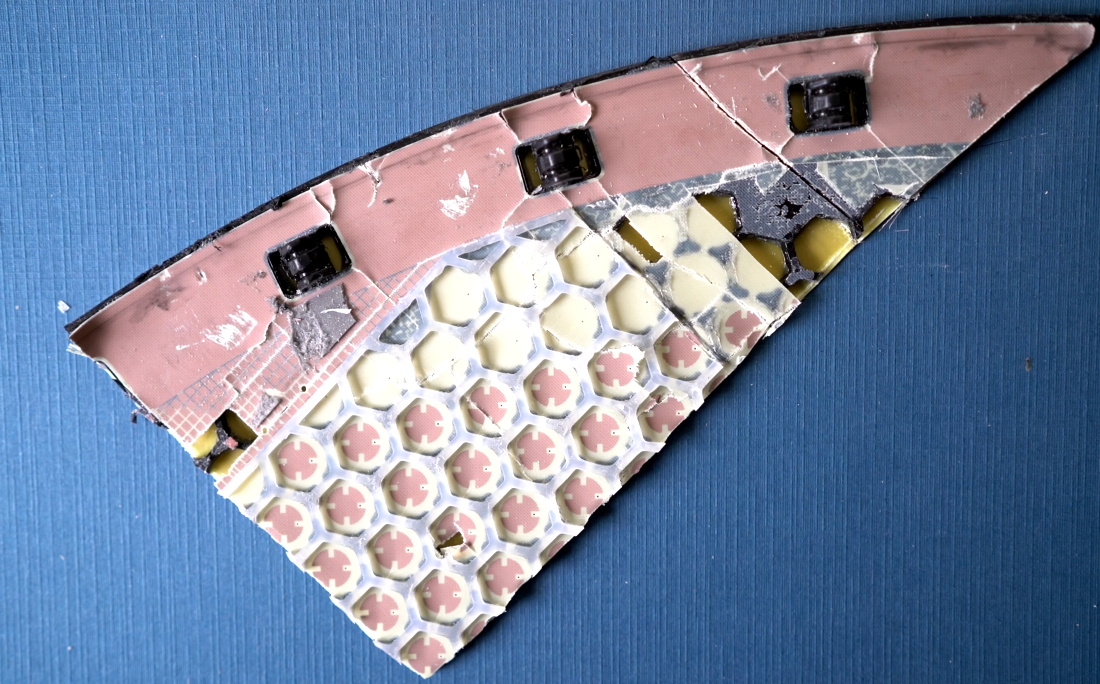
As with everything else he’s involved with, Elon Musk has drawn a lot of criticism for his Starlink satellite-based internet service. The growing constellation of satellites bothers astronomers, terrestrial ISPs are worried the service will kill their business model, and the beta version of the Starlink dish has been shown to be flakey in the summer heat. But it’s on equipment cost where Musk has taken the most flak, which seems unfair as the teardowns we’ve seen clearly show that the phased-array antenna in the Starlink dish is being sold for less than it costs to build. But still, Musk is assuring the world that Starlink home terminals will get down in the $250 to $300 range soon, and that the system could have 500,000 users within a year. There were a couple of other interesting insights, such as where Musk sees Starlink relative to 5G, and how he’s positioning Starlink to provide backhaul services to cellular companies.
Well, this is embarrassing. Last week, we mentioned that certain unlucky users of an obsolete but still popular NAS device found that their data had disappeared, apparently due to malefactors accessing the device over the internet and forcing a factory reset. Since this seems like something that should require entering a password, someone took a look at the PHP script for the factory restore function and found that a developer had commented out the very lines that would have performed the authentication:
    function get($urlPath, $queryParams=null, $ouputFormat='xml'){
//        if(!authenticateAsOwner($queryParams))
//        {
//            header("HTTP/1.0 401 Unauthorized");
//            return;
//        }
It’s not clear when the PHP script was updated, but support for MyBook Live was dropped in 2015, so this could have been a really old change. Still, it was all the hacker needed to get in and wreak havoc; interestingly, the latest attack may be a reaction to a three-year-old exploit that turned many of these devices into a botnet. Could this be a case of hacker vs. hacker?