When we think of physics experiments, we tend to envision cavernous rooms filled with things like optical benches, huge coils in vacuum chambers, and rack after rack of amplifiers and data acquisition hardware. But it doesn’t have to be that way – you can actually perform laser interferometry with a single component and measure sub-micron displacements and more.
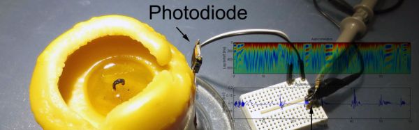
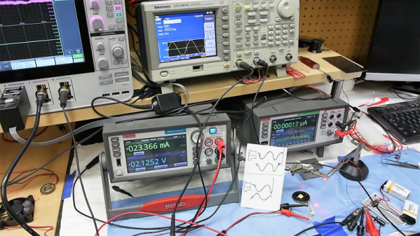
The astute viewer of [Ben Krasnow]’s video below will note that in order to use the one component, a laser diode, as an interferometer, he needed a whole bunch of support gear, like power supplies, a signal generator, and a really, really nice mixed-signal oscilloscope. But the principle of the experiment is the important bit, which uses a laser diode with a built-in monitoring photodiode. Brought out to a third lead, older laser diodes often used these photodiodes to control the light emitted by the laser junction. But they also respond to light reflected back into the laser diode, and thanks to constructive and destructive interference, can actually generate a signal that corresponds to very slight displacements of a reflector. [Ben] used it to measure the vibrations of a small speaker, the rotation of a motor shaft, and with a slight change in setup, to measure the range to a fixed target with sub-micron precision. It’s fascinating stuff, and the fact you can extract so much information from a single component is pretty cool.
We really like [Ben]’s style of presentation, and the interesting little nooks and crannies of physics that he finds a way to explore. He recently looked at how helium can kill a MEMS sensor, an equally fascinating topic.
Continue reading “[Ben Krasnow] Builds A One-Component Interferometer”


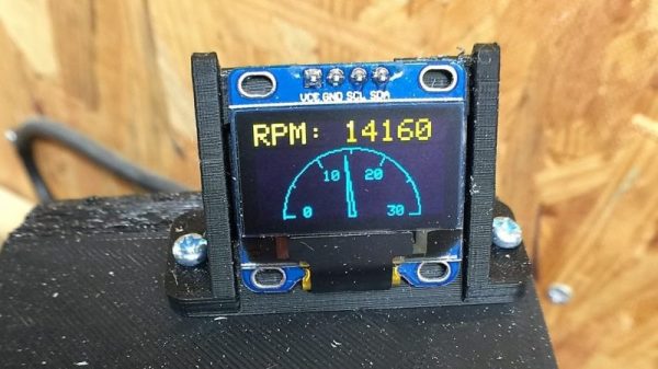
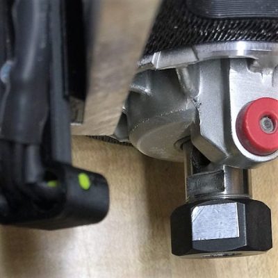 The CNC router in question is the popular Sienci, and the 3D-printed brackets for the photodiode and LED are somewhat specific for that machine. But [tmbarbour] has included STL files in his exhaustively detailed write-up, so modifying them to fit another machine should be easy. The sensor hangs down just far enough to watch a reflector on one of the flats of the collet nut; we’d worry about the reflector surviving tool changes, but it’s just a piece of shiny tape that’s easily replaced. The sensor feeds into a DIO pin on a Nano, and a small OLED display shows a digital readout along with an analog gauge. The display update speed is decent — not too laggy. Impressive build overall, and we like the idea of using a piece of PLA filament as a rivet to hold the diodes into the sensor arm.